4
C. WIRING
WARNING: THE POSITIVE VENTILATION UNIT AND ANY ANCILLARY CONTROL EQUIPMENT
MUST BE ISOLATED FROM THE POWER SUPPLY DURING THE INSTALLATION OR
MAINTENANCE.
THE Lo-Carbon PoziDry Compact (POSITIVE VENTILATION UNIT) MUST BE EARTHED.
Mains supply voltages (220-240V ac) are present in this equipment which may cause death or serious injury by
electric shock. Only a qualified electrician or installer should connect the power supply to this unit.
The Lo-Carbon PoziDry is designed for operation from a single-phase alternating current source (220-240V AC).
An integral mains flying lead is connected to the unit for connection to a 3A switched fused spur. It should be
capable of disconnecting all poles, having a contact separation of at least 3mm.
If a heater switch is required in order to turn the heating element on and off during Trickle ventilation operation, a
single pole, one-way switch can be wired in to the Lo-Carbon PoziDry heater version terminal block by removing the
link between H & L and replacing with the heater switch wires; thus making and breaking the live supply to the
heater. There is a 16mm hole provided with a plug stopper fitted in the front panel of the Lo-Carbon PoziDry. This
should be removed and replaced with a suitable cable gland. The heater switch cable can be fed through the cable
gland and into the terminal strip. The heater switch cable should be located under the cut-out in the terminal cover
together with the fan and thermistor cables when the terminal cover is replaced. The switch, cable and cable gland
which are not supplied should be rated at 3 amps.
TO CONNECT A POWER SUPPLY:
•
Ensure the local AC power supply is isolated.
•
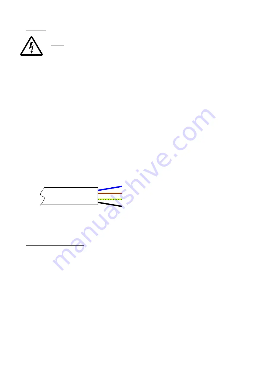
The product has a pre-wired flying lead. Connect the brown core to Live, blue core to Neutral, green/yellow to
Earth, and black to LS (for 100% PURGE if required).
•
Use cable clamps and clips to secure the cable, as appropriate.
•
Maximum heater power 300W and motor power 15W
D. START UP SEQUENCE
The Lo-Carbon Pozidry Compact will perform a start up test procedure on
every
power up.
During this sequence, the following will occur:
1) Motor goes to full speed.
2) LED segments light up one at a time until all 7 are lit.
3) Potentiometers and Thermistor are measured and the motor pulses counted. If any of these sources shows an
error, then it is displayed. A list of error codes is shown below.
4) Motor goes to lowest (Normal) speed; if the motor stalls then an ‘error’ is displayed. Otherwise the display shows
'n' indicating Normal speed.
5) After 10 seconds the heater is turned on, the display now shows 'h.' for heat.
6) After 20 seconds (to allow the element to warm up) the heater is turned off, the motor goes to maximum Normal
speed to cool the heater and the display shows 'b' indicating Normal speed.
7) After 10 seconds the display shows the elapsed hours. Six digits are displayed sequentially immediately
after the ‘b’. For example, 000048 would indicate 2 complete days has elapsed.
8) The unit exits the test mode and runs at the appropriate rate whilst displaying a rotating segment display. The rate
will depend upon ambient temperature.
Blue – Neutral
Brown – Live
Green/yellow – Earth
Black – Switched Live (LS)


