4
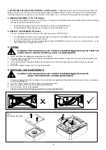
4. Remove the Skirt and pass the supplied screw fully through the flange of the base housing. Then attach the 3
supplied Panel Clips (Fig 5). and partially screw into place until they are properly retained (allowing enough gap
for the panel thickness).
5. Set-up the appropriate speed selection and other features as outlined in
Section B SETUP.
6. Attach the ducting to the Spigot and locate into the hole in the panel, ensuring the cable is fed into the Base
Housing and the Panel Clips spring out behind the panel.
7. Secure into position by carefully tightening the Panel Clips. It maybe necessary to hold the product centrally in
the hole while tightening so that no gaps are seen once the cover is on.
IMPORTANT: If power tools are used,
set them to the minimum torque setting or preferably use a manual screwdriver. Do not over tighten.
8. Ensure the Impeller rotates freely.
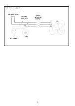
9. Select and follow the appropriate wiring diagram in
Section C WIRING.
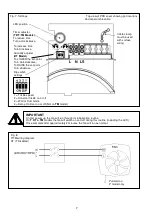
10. Replace the inner grille ensuring that the PIR sensor cable (TM model only) is reconnected to the PIR sensor
PCB (Fig 6)
.
Replace the front panel.
11. Switch the mains power supply on and check the fan is operating correctly.
WALL MOUNTING (Surface)
For wall installations a Wall Kit (25 41 02 White / 25 41 00 Brown) can be used.
1. Cut a 115mm.
∅
hole through the wall, ensuring that there is sufficient space for the product to be installed and
that the filter (if fitted) can be removed for maintenance.
2. Insert the wall sleeve with the smaller diameter sleeve on the room-side and cement both ends into position flush
with the wall faces. The wall sleeve should be angled downwards, away from the fan, to allow any condensation
to drain to the outside wall.
3. Outside Grille: Using the Back Plate as a template, mark the fixing hole centres on the wall. Drill and plug the
wall and fix the Back Plate into position.
4. Fix the Outside Grille on to the Back Plate (screws provided). Ensure the louvres are pointing downwards.
5. Removing the grille, Firstly remove the front cover by carefully pulling each corner of the front panel until it is free
to be removed from the inner grille (Fig 1). Unscrew the two screws at the bottom of the inner grille. The screws
will remain in the inner grille but will be loose when the grille is ready to be removed (Fig 1).
Lift the inner grille
from the bottom edge ensuring not to damage the sensor cable (TM model only) attached to the front assembly
and Base Housing (Fig 6).
6. Remove the Spigot Ring from inside the carton and clip over the Spigot Adaptor making sure the lip on the
Spigot Ring locates firmly inside the groove on the Spigot Adaptor (Fig 2). Ensure that the Spigot Adaptor is
firmly located onto the Base Housing and the shutter is still securely fastened and fully functional.
7. Set-up the appropriate speed selection and other features as outlined in
Section B SETUP.
8. Using the Base Housing as a template, mark the fixing hole centres on the wall, carefully sliding the spigot into
the Wall Liner. Secure the Base Housing into position using the screws and fixings provided ensuring the Skirt is
located correctly into the Base Housing (Fig 3)
9. Ensure the Impeller rotates freely.
10. Select and follow the appropriate wiring diagram in
Section C WIRING.
12. Replace the inner grille ensuring that the PIR sensor cable (TM model only) is reconnected to the PIR sensor
PCB (Fig 6)
Replace the front panel.
13. Switch the mains power supply on and check the fan is operating correctly.
B.
SETUP
WARNING: THE FAN AND ANCILLARY CONTROL EQUIPMENT MUST BE ISOLATED FROM THE
POWER SUPPLY DURING THE INSTALLATION / OR MAINTENANCE.
1. SELECTING THE CONSTANT TRICKLE OPTION -
Switch dip switch 2 into the ON position to activate the constant
trickle operation. To disable the constant trickle option, move dip switch 2 into the OFF position (Fig 7).
2. SELECTING THE TRICKLE SPEED (if enabled)
This will determine the speed at which the fan will run continuously if the constant trickle speed option is enabled (1 above).
•
Low trickle speed – Switch dip switch 1 into the OFF position (Fig 7).
•
High trickle speed – Switch dip switch 1 into the ON position (Fig 7).
3. SELECTING THE INSTALLATION RUNNING MODE
This will determine the speed at which the fan will run when activated by either the Pull-cord/LS line/Humidity/PIR.
•
Wall mode – Switch dip switch 3 into the OFF position (Fig 7)
•
Ducted mode – Switch dip switch 3 into the ON position (Fig 7)
IMPORTANT
On first power up, the fan will run through its initialization routine.
On
T
,
HT
&
TM
models the fan will switch on and off during this routine (Including the LED)
Once complete after approximately 2 minutes, the fan will run as normal.
Summary of Contents for Lo-Carbon Solo Plus HT
Page 8: ...8 Fig 9 T HT wiring diagram...
Page 11: ...11 Notes...

