4
Fan
1 Phase Supply
(220-240V 50Hz).
FUSE
Switched
Fused Spur
Pullcord
L
~
N
8V = Low Speed for
a Utility Room
12V = High Speed for
a Kitchen
12V
N
L
8V
0V
~ N
E
0V
8V
12V
8V = Low Speed for
a Utility Room
12V = High Speed for
a Kitchen
Fan
L
LS
N
Timer Adjuster.
B.
WIRING.
WARNING: THE FAN AND ANY ANCILLARY CONTROL EQUIPMENT MUST BE ISOLATED
FROM THE POWER SUPPLY DURING THE INSTALLATION / OR MAINTENANCE.
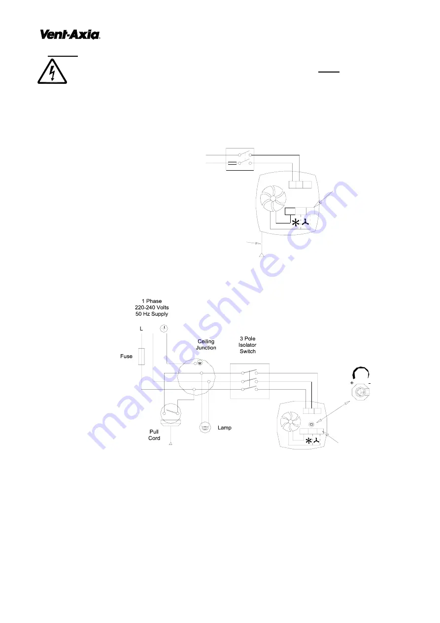
1. Select and follow the appropriate wiring diagram (Fig. 2-4).
2. Check all connections have been made correctly and ensure all terminal connections and cable clamps are
securely fastened.
3. The cable entry must be made using the cable grommet.
4. Ensure the impeller rotates and is free from obstructions.
Fig. 2.
LoWatt U/KP
(45 91 23) Pullcord Model.
Select the wiring configuration
required for the Utility or Kitchen.
Fig. 3.
LoWatt U/KT
(45 91 24) Timer Model.
Select the wiring configuration
required for the Utility or Kitchen.
Timer Adjustment.
The overrun time period is factory set to 15 minutes. The overrun time period may be adjusted from 5-30 minutes,
by altering the adjuster on the Fan PCB.
Before adjusting the timer, switch off the Mains Supply.
1. Remove the Indoor Grille [A]. Loosen the screw (top middle) of the Grille, to release front grille gently lever the
Grille downwards away from the Inner Cover [B].
2. Remove Inner Cover [B]. Insert a small bladed screwdriver into the slot on the sides of the Cover, push the
release catch in and gently lever the cover away from the Base Housing [D].
3. To REDUCE the operating time, turn the Timer Adjuster CLOCKWISE.
4. To INCREASE the operating time, turn the Timer Adjuster ANTI-CLOCKWISE.
5. Replace the Inner Cover and Indoor Grille.
6. Reconnect the mains supply.


