9
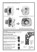
Fig.4. Removing the grille for wiring and setting the controls
Pull front panel as shown.
Loosen screws – DO NOT REMOVE FROM GRILLE
(the screws are self-retaining)
Pull inner grille away from housing as shown.
When replacing grille, ensure the flow sensor is
aligned with the corresponding slot in the grille.
Fig.5. Controls
Note:- Before changing any of the dipswitch positions the fan
must be isolated from the power supply.
Trickle speed (JP1) (All models)
8l/s
= Remove Jumper Connector
6l/s
= Replace Jumper Connector (factory set)
(For
13l/s
, permanently link terminal connections L to LS)
Airflow detection system
(All models)
Auto sensing mode
= Dip switch 1 (SW1) into the
on position to turn on airflow detection system.
Manual mode
= Dip switch 1 (SW1) into the off
position to turn off airflow detection system
(factory set)
Silent running boost mode
(TP & HTP only)
Off
= Dip switch 2 (SW1) in the off position
Traditional mode (factory set)
On
= Dip switch 2 (SW1) in the on position
This feature will delay the boost operation
for a maximum of 20 minutes.
(see C.SETUP section Item 9)
1
2
ON
1 2
ON
1
2
ON
1 2
ON
JP1 - Trickle
speed
SW1 – Airflow
detection system
and Silent running
boost
JP2 - (HTP
ONLY)
Fixed timer
enable/
disable
jumper
Adjuster for
timer (TP) or
humidistat
(HTP)


