Appendix
Sentinel Kinetic MVHR Installation & Commissioning
45
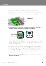
Wireless Enable kit (consists of Wireless Receiver and one Wireless Switch).
1
.
To fit the Wireless Receiver remove the Front, Rear and Bottom Case panels, insert the ribbon cable plug
into terminal J9 and fit the Receiver assembly to the main PCB with the double sided pads provided.
2.
Open the Wireless Switch by inserting a flat bladed screwdriver into the slot at the bottom and fit two AA
batteries to the transmitter, removing any plastic tabs between battery and terminal.
3.
Ensure that the system address, set by the 6-way DIP switch on the Wireless Switch PCB matches that on
the Wireless Receiver PCB. For multiple systems in close proximity to each other, the system addresses
need to be different. The Wireless Switch PCBs also have a 2-way DIP switch to set the transmitter address.
Up to four Wireless Switch’s can be used to control any one unit. The Wireless Switch address needs to be
different for each Switch in a system.
4.
Accessories can be connected to the volt-free and light switch connections so that the transmitter sends a
boost signal on the accessory's behalf. The LED light above the
button will illuminate when a button is
pressed. Pressing the
button will send a signal wirelessly to the unit, telling it to run at Boost speed for 15
minutes. Pressing the
and
buttons will adjust the overrun time in 5 minute increments. The LCD will
count down the time in minutes. If more than one of the wireless transmitters are calling for Boost speed, the
unit will prioritise the longest overrun time period requested. The unit may continue to run at Boost speed
after the timer has timed out if another accessory or switch is calling for Boost speed.
5.
Purge Feature: Pressing and holding the
button for more than 5 seconds will send a signal telling the unit
to run at Purge speed for 2 hours.
MAX
AA
AA
6-way DIP
Switch
2-way DIP
Switch
Wireless Receiver
Summary of Contents for Sentinel Kinetic B 438222
Page 47: ......

