J.
Young children should be supervised to ensure that they do
not play with the appliance.
IMPORTANT:- ONLY CONNECT TOGETHER PRODUCTS FROM THE SOLO PRO
SELV RANGE SINCE THE FANS ARE SPECIALLY DESIGNED TO WORK ON 12V
AC AND ARE NOT COMPATIBLE WITH OTHER VENT-AXIA CONTROLLERS. DO
NOT CONNECT MORE THAN ONE FAN TO THE CONTROLLER.
DESCRIPTION
The Solo Pro SELV fan is an extract fan for bathrooms and toilets specifically designed
for ducted applications. Pullcord, Timer, and Humidity options are available.
ACCESSORIES
(not supplied)
WALL FITTING KIT
A range of white (stock ref. 254102) or brown (stock ref. 254100) 100mm wall kits are
available for installing into most walls using telescopic liners supplied.
WINDOW FITTING KIT
A window fitting kit is available. Stock reference 11461685.
A. INSTALLATION
SITING THE CONTROLLER
1.
The controller must not be installed in a shower cubicle or enclosure. It must be
sited away from direct sources of water spray and out of reach (1.5m) of a person
using a fixed bath or shower.
2.
Site away from direct sources of heat. Ambient temperature range 0 to 40ºC. Do
not site in an area containing excessive levels of grease.
3.
Decide where to site the controller and fan (see section siting the fan), and work
out the required cable runs.
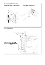
PANEL/CEILING MOUNTING –
(FIG.4.)
1.
Cut a 105mm diameter hole.
2.
Remove the front panel by carefully pulling it away from the fan.
3.
Loosen the two self-retaining screws and remove the inner cover by carefully
pulling it away from the housing.
4.
Remove the impeller by carefully pushing the retaining clips together.
5.
Remove the PCB cover by loosening the two screws and pulling it out of the fan
housing.
6.
Mark the screw centres through the holes in the fan back plate. Drill, plug and
screw into position. Attach ducting and back draught shutters as required for the
installation.
7.
Wire the fan as described in Section B-Wiring. Adjust any settings as required
(see Section C-Setup).
8.
Replace the PCB and inner covers and tighten the retaining screws.
9.
After installation, ensure impeller rotates freely. Replace the front panel.
Summary of Contents for Solo Pro SELV Series
Page 2: ......
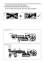
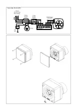
Page 8: ...Fig 3 Solo Pro SVHTP N L N Fan Controller LS L N SELV Supply 12V 50Hz 3A UK Ls LS 0 12V...
Page 11: ......

