background image


5


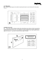
PREPARATION FOR INSTALLATION (Dismantling) 


D1 

Place the fan unit, external grille downwards, on a flat surface.  

D2 

Unscrew grille securing screw located at the top of the grille. Remove internal grille. 

D3 

Slacken the two safety catch screws on the face of the housing. Depress the side catches. 

D4


Lift off the housing. 

D5 

Remove the top cover from its housing. Check rating label to ensure that the fan unit is the correct voltage.  

D6


Ease back the motor support safety catch located in the left-hand top corner of the base housing. Rotate 
motor support assembly anticlockwise until the bayonet catches disengage from the base housing. 

D7 

Withdraw motor support assembly and place with the impeller downwards. 

D8 

Separate the base housing from the external grille assembly. 


Summary of Contents for VA 150 A

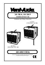
Page 1: ...TIONS IN CONJUNCTION WITH ILLUSTRATIONS PLEASE SAVE THESE INSTRUCTIONS Installation and Wiring Instructions 220 240V 1 50Hz VA150 A STOCK Ref 153110B VA150 P STOCK Ref 152110B VA 150 A VA 150 P WINDOW...

Page 2: ...2...

Page 3: ...ate standards of your country and MUST be installed by a suitably qualified person B The Fan should be provided with a local all pole isolator switch having a contact separation of at least 3mm C Ensu...

Page 4: ...s with a fixing thickness up to 32mm with the screws provided When fixing thickness exceeds 32mm the unit should be secured with Extended Fixing Rods available as an accessory item 56 81 04 If the uni...

Page 5: ...catches D4 Lift off the housing D5 Remove the top cover from its housing Check rating label to ensure that the fan unit is the correct voltage D6 Ease back the motor support safety catch located in th...

Page 6: ...er lugs and around the spigot E2 From the outside place the exterior grille assembly over the projecting spigot ensure that the grille louvers are slanting downwards E3 From the inside insert the four...

Page 7: ...internal grille Locate the bottom edge first and then engage the top Tighten the securing screw at the top of the grille E8 Switch on the mains supply Check the fans operation VA150 P 1 Pull the pullc...

Page 8: ...e through the clamp 2 Connect the LIVE Brown to the terminal L and NEUTRAL Blue to the terminal N 3 Tighten the cable clamp screws evenly ensuring a secure grip on the outer sheath of the cable The Fa...

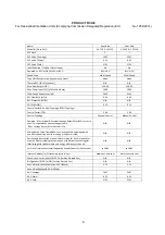
Page 9: ...trol Typology Manual Control Manual Control Declared Max Internal External Leakage Rates for BVUs or carry over for regenerative heat exchangers only Ext Leakage Rates for Ducted UVUs N A N A Mixing R...

Page 10: ...10...

Page 11: ...11...

Page 12: ...rge provided that the product 1 Has been installed and used in accordance with the instruction given with each unit 2 The electricity supply complies with the rating label 3 Has not been misused negle...

Reviews: