11126 McCormick Road, Hunt Valley, MD 21031 | 800-851-4965 | sales@ventev.com | ventevinfra.com |
Rev. 022822
23
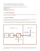
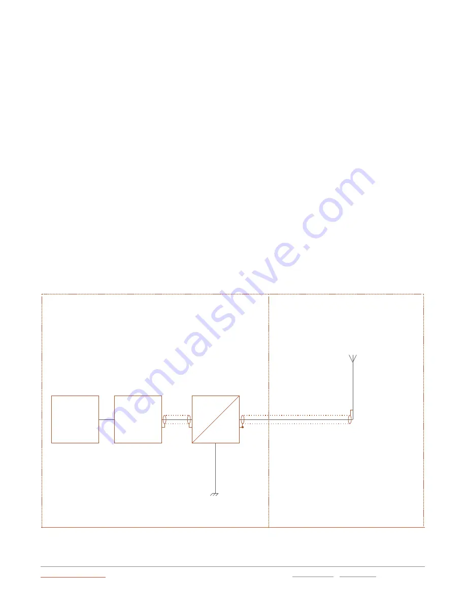
NON HAZARDOUS AREA
HAZARDOUS AREA
Total Effective Radiated RF
Power from Antenna Must
Antenna
Be Less Than Threshold Power
(No Certification Required)
As Defined in Section 3.1
U
m
=253V
Coaxial
Cable
Coaxial
Cable
Antenna Installed to IEC 60079-14:2014
Clause 16.2.3
iSOLATE501
Earth Connection
per Figure 1
Provides Galvanic
Isolation
iSOLATE501
TRANSMITTER
POWER SUPPLY
U
m
=253V
3.10.1
Example of RF Threshold Power Calculation
The following example shows how the RF threshold power may be calculated:
Maximum Transmitter Output Power (from transmitter datasheet) =
20dBm (100mW)
Coaxial Cable Loss =
2dB
Antenna Gain =
5dBi
Threshold Power =
20dBm
–
2dB + 5dBi
Threshold Power =
23dBm (200mW)
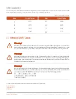
3.11
Antenna Requirements
Antennas connected to the Hazardous Environment Enclosure intrinsically Safe RF outputs must be assessed as
‘simple
apparatus’ in accordance with IEC 60079
-11.
3.12
Antenna Installation
Antennas approved by Ventev for use with the Hazardous Environment Enclosure may either be fitted directly to the
RF connectors of the Hazardous Environment Enclosure, or via a length of coaxial cable.
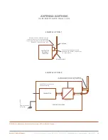
If antennas are sited remotely from the Hazardous Environment flameproof enclosure, any metallic parts of the antennas
must be isolated from earth by > 500Vr.m.s, to prevent hazardous earth currents from flowing in the coaxial cable.
FIGURE 10.1: Hazardous Environment Enclosure IS RF Installation Diagram

