background image

The usage of Child Laser Scanners (PR-DA-001-0582) in combination with Parent Laser Scanners should be considered when the user wants to monitor
multiple planes and/or areas that may be obstructed or not visible by a single Parent Laser Scanner. The Child Laser Scanner specifications are as follows:

Maximum safe zone: 5.5m radius.
Maximum warning zone: 40m radius.
Detection angle: 275o.
Total/partial dynamic muting available.
Zone switching (bank switching) available.
Daisy-chain cable included.
Maximum units in cluster: 3 (i.e. Parent S 3 Children Scanners).

How to Configure a Parent-Child Cluster

To configure a laser scanner cluster comprised of a Parent Scanner and up to three Child Scanners, perform the following steps:

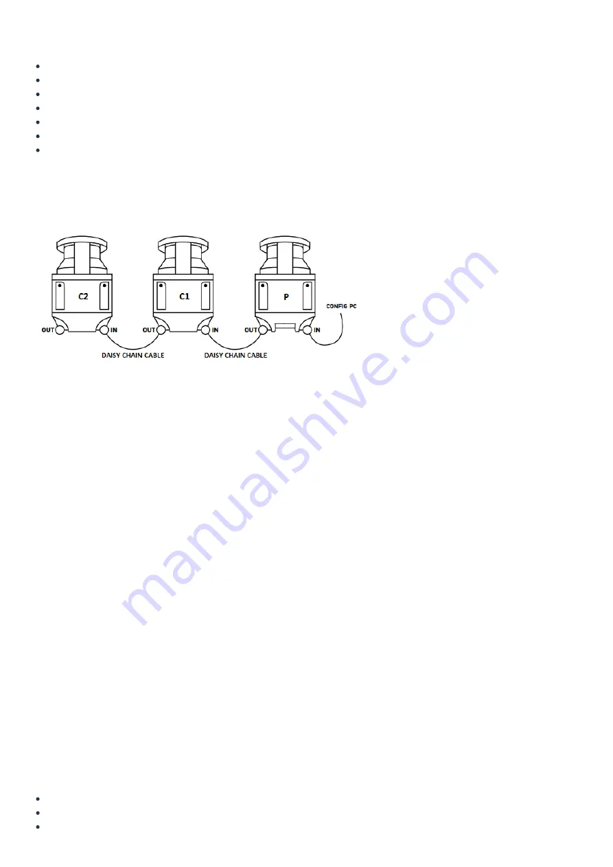
1. Connect the scanners as illustrated below using the included daisy-chain cables.

2. Follow steps 2 to 6 of the Getting started section for the Parent scanner.
3. Select the Parent Scanner on the left side of the DLSentinel window and click the white arrow at the top-right corner of the screen.
4. Configure the Parent Scanner using the Configuration drop-down menu located in the top-left corner of the screen. See the Parameters’ configuration
section of the Parent Scanner for more information.
5. Select a Child Scanner on the left side of the DLSentinel window and click the white arrow at the top-right corner of the screen.
6. Under the Configuration drop-down menu, only configure the Detection and Zones items.
7. Repeat steps 5 and 6 for each Child Scanner in the cluster.
8. Once satisfied with the configuration, click the 

Next white arrow in the top-right corner of the screen. Then click  Load to upload the configuration to the

area scanner cluster. If prompted to enter a password, the default password is “admin” (this can be changed later). A warning will appear saying “Scanner
status change in Off-Duty, continue?”. Select OK. Once the configuration is uploaded, click 

Accept to finalize the process.

9. To ensure everything is working as expected, click 

Monitoring while plugged into the scanner to see a live feed of the scanners functioning.

For more information on various display icons that may appear on the Laser Scanner screen, refer to Datalogic’s Quick Guide for the SLS-M5-0812-E (Parent
Scanner) & SLS-R5-E (Child Scanner) models.

Troubleshooting

If the parent and the child scanners are not able to communicate to each other or cannot be configured together, make sure that they are all on the same
firmware version.

If a child scanner is disconnected or missing from the cluster that has been programmed and uploaded, the parent scanner will fall into an endless power
cycle loop. To solve this, either reconnect the missing scanner(s) or disconnect all children scanners and upload a parent-only configuration to the parent
scanner (follow steps 2 to 6 in Getting started for the parent scanner) to regain access to the parent scanner. Then, reconnect the children scanners to the
cluster and reconfigure the cluster as desired.

Light Curtain

Description

The Light Curtain (PR-DA-001-0295 & PR-DA-001-0296) is a useful device to increase safety in various industrial applications. It is generally used to monitor and
control the entry and/or exit of objects across a safety barrier. If an unwanted object or person crosses the safety barrier, the Light Curtain will stop the
machine it is connected to. It also features total muting. In order to use the Light Curtain with MachineMotion2, a Safety Module (CE-SA-008-0000__2) is
required, please refer to the installation instructions below.

The Light Curtain specifications are as follows:

Resolution type: 4 (finger and hand protection).
Resolution: 30 mm.
Monitored height: 750 mm.

Summary of Contents for PR-DA-001-0295

Page 1: ...rge areas while remaining discreet and unobstructive It will stop a machine if any undesired person or object crosses its safety zone It features a couple of useful functionalities such as muting automatically deactivates the safety status of the whole system total muting or part of it partial muting to let material pass through Another useful function is bank switching ability to switch between t...

Page 2: ...PC open the DLSentinel software and navigate to Scanner Discovery Your scanner should appear on the left panel Select your scanner A warning window may appear asking to change your IP address Select OK 5 Align the IP address To align the IP address make sure DHCP is set to Static Verify that the last number of the IP Local address is different from the last number of the IP address In figure 3 the...

Page 3: ...drop down menu For each item on the drop down menu enter the desired values in the appropriate fields highlighted in yellow More details are provided for each parameter below Figure 4 Configuration settings page 1 Outputs 1 Auto Reset can be set to ENABLED or DISABLED If the Laser Scanner boots with an error such as both zones are activated or no zones are activated this function will automaticall...

Page 4: ...parameter is used to avoid delays between signal switching that could result in error states A value of 510 ms is typically suitable for most devices However it is recommended to decrease this delay as much as possible according to the device controller s response time 3 Inputs 1 Recovery time msec is the time delay between the object leaving the protected area and the OSSDs achieving the NORMAL O...

Page 5: ...For no timeout set this value to 0 The maximum value is 1080 minutes 18 hours 4 Detection 1 Number of scans controls the number of scans required to validate a detection This parameter has a direct impact on Response time more scans results in a longer response time 2 Detection capability mm is the ability to detect an object of given dimensions within the detection zone Objects greater than or eq...

Page 6: ... frame or wall Then set the tolerance If the reference point moves outside the permitted tolerance the OSSD will switch to an OFF state 6 NOTE According to safety guidelines when a laser scanner is monitoring a vertical plane the safety zone should have a maximum gap of 180 mm from the bottom and a minimum height of 1400 mm when there are no height restrictions 7 Once satisfied with the configurat...

Page 7: ...ault password is admin this can be changed later A warning will appear saying Scanner status change in Off Duty continue Select OK Once the configuration is uploaded click Accept to finalize the process 9 To ensure everything is working as expected click Monitoring while plugged into the scanner to see a live feed of the scanners functioning For more information on various display icons that may a...

Page 8: ...idelines a light curtain barrier should have a maximum gap of 180 mm from the bottom and a minimum height of 1400 mm when there are no height restrictions The same safety guidelines apply for a laser scanner mounted vertically i e monitoring the vertical plane Connecting to MachineMotion 2 Laser Scanner The steps to connect the Laser Scanner to MachineMotion 2 via the Safety Module are as follows ...

Page 9: ...Figure 13 Laser Scanner Parent only wiring diagram ...

Page 10: ...E SA 105 0001 3 Connect a MachineMotion 2 Safety Extension Cable CE CA 102 5001 to the Safety Module s SAFETY OUT connector and MachineMotion 2 s SAFETY IN connector 4 If muting is required connect the muting sensor in pairs to the Muting Sensor Y Adapter CE SA 107 0001 Then connect the adapter to the Safety Module via the MUTING 1 and or MUTING 2 connectors Note If no other safety devices are bei...

Page 11: ...ensors must be placed according to the material s length and speed so they can recognize passing objects such as pallets vehicles etc Generally two muting sensors are used and they must be triggered sequentially It is also possible to use four muting sensors where sensors A1 and A2 are connected together and B1 and B2 are connected together Unidirectional muting is used for objects entering or lea...

Page 12: ...ss the safety zone Figure 17 Bidirectional muting Muting for Laser Scanner The Laser Scanner can perform both unidirectional and bidirectional muting In unidirectional muting the m coefficient must be defined This coefficient controls how long the safety zone remains off before reactivating In other words it defines the activation time delay following a muting event The m coefficient is a multiple...

Page 13: ...rtain The Light Curtains can only perform bidirectional muting which requires four sensors Once muting is activated the entire safety zone will be muted total muting Partial muting cannot be used with the Light Curtains Figure 19 Safety Module V2 with Light Curtains block diagram with muting ...

Page 14: ......

Reviews: