background image

Figure 36

Figure 37

D-3

SERVICE & MAINTENANCE

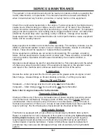
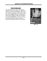
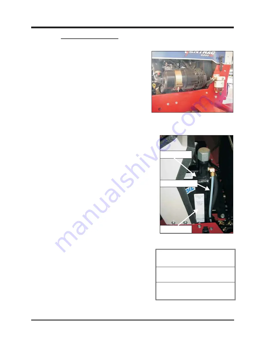
AIR INTAKE FILTER

The air intake filter on the Vanguard engine
models is located on the left side

(Figure 36)

. This

external filter assembly has 4 stages of filtration.

1

) An intake turbo.

2

) A dust unloading valve. (1 &

2 require no servicing.)

3

) A prefilter.

4

) a final

cylinder element.

Note:

Under normal operating conditions, the

inner filter does not need be replaced. Never
operate with inner filter removed.

Kawasaki engine air intake filters are located
above the engine and have a prefilter band over a
paper element. The paper element should be
changed if its appearance is dirty or light is no
longer visible through the element when held up to
a light source. See engine manual for more
details.

Note:

Kawasaki does not recommend oiling the

foam prefilter (outer) element.

Expansion tank

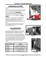
HYDROSTATIC TRANSMISSION OIL

The top oil reservoir for the hydrostatic
transmission oil is located under the hood near the
right side of the dash. Check oil level when engine
is cold. Find the oil level in the plastic sight tube
next to the expansion tank, and check that it is
within the proper range indicated by the oil level
decal. This is important for proper performance
and life of the hydrostatic system.

NOTE:

Non-compliance to this specification may void
the VENTRAC 4200 VXD warranty.

Note: Generally the hydrostatic oil level
remains constant except when:

1) New attachments are added that use

the auxiliary oil circuit.

2) There is an oil leak.

NOTE: Changing of hydrostatic oil is Not
recommended except in the event of
excessive contamination.

Plastic sight tube

Oil level decal

REQUIRED OIL

SPECIFICATION

Ventrac Hydro•Torq XL

synthetic hydraulic oil

System Capacity: Front - 12 quarts

Rear - 4 quarts

Summary of Contents for 4200 VXD

Page 1: ...TRACTOR 4200 VXD Serial 1001 2928 OWNER OPERATOR S MANUAL Venture Products Inc Orrville OH REVISED 04 18 07 2ND EDITION 09 10027 ...

Page 2: ...________ Day __________ Year ____________ Model Number _______________________________________________________ Serial Number ________________________________________________________ Dealer ______________________________________________________________ Dealer Address _______________________________________________________ _______________________________________________________ Dealer Phone Number _...

Page 3: ... Hitch Lock C 7 Weight Transfer C 8 Front Hitch PTO C 8 PTO Engagement C 9 Lights C 9 Starting Procedure C 10 Attaching Attachments C 11 Dual Wheel Mounting KTA style C 12 13 Operating on Slopes C 14 MAINTENANCE SERVICE SECTION D Service Schedule D 1 Engine Oil D 2 Radiator D 2 Air Intake Filter D 3 Hydrostatic Transmission Oil D 3 Rear Transaxle D 4 Hydrostatic Oil Filter D 5 Fuel Line Filters D ...

Page 4: ...TABLE OF CONTENTS iv ELECTRICAL DIAGRAMS SECTION E Electrical Components E 1 Kawasaki 27 HP E 2 Vanguard Gas E 3 Vanguard Diesel E 4 WARRANTY ...

Page 5: ...uxiliary function SDLA through an integrated control system in arm chair position Its position on the right side of the operator is always comfortable and accessible Single high low range selector lever enables operator to use low range for operating attachments and high range for transport Front end Minute Mount hitch and optional category 1 three point rear hitch makes the Ventrac 4200 VXD a pow...

Page 6: ...one 10 and one 25 micron filter Tires Standard Tire Titan HD 22 x 12 x 8 21 inch actual diameter Optional Bar Tire Goodyear Rawhide 21 x 11 x 8 Optional Turf Tire Carlisle Turf Master 22 x 11 x 10 Dimensions Wheelbase 43 inches Length 79 inches Height to Top of Roll Bar 67 inches Width with Single Tires 48 inches Width with Dual Tires 70 inches Dimensions may vary slightly for each tire option Wei...

Page 7: ...y hazardous situation which if not avoided will result in death or serious injury This signal word is limited to the most extreme cases CALIFORNIA Proposition 65 Warning CALIFORNIA PROPOSITION 65 Battery Warning The engine exhaust from this product contains chemicals known to the State of California to cause cancer birth defects or other reproductive harm Diesel engine exhaust and some of it s con...

Page 8: ...rocedure Ensure that all bystanders are clear of the tractor and attachment before operating Be especially careful and observant if other people are present Never assume that bystanders will remain where you last saw them Always look in the direction the tractor is moving Never direct the discharge of any attachment in the direction of people animals buildings vehicles or objects of value Immediat...

Page 9: ...tificial light Use Extra Care Stay alert for holes hidden objects and uneven terrain Use extra care when you come to shrubs trees or other objects that may block your vision Clear from work area objects that may be thrown If you hit an object stop machine and check for damage Avoid adverse ground conditions which can limit performance and stability of equipment and could result in serious injury o...

Page 10: ...hot DO NOT touch The Roll Bar is provided for your protection Always use seat belt with roll bar to minimize chance of injury from an accident See Warning on C 5 for fold down roll bar exceptions Use caution when handling the battery Shield eyes as explosive battery gases and acid can cause injury or blindness Flush eyes immediately with water and seek medical attention Keep sparks flames and ciga...

Page 11: ...s the easy to use Minute Mount Front Hitch and PTO drive that makes frequent use of many different attachments a breeze The tractor is designed with a low bi level foot platform and openness between dash and fenders to make entering and exiting easy for the operator from either side however right side entering and exiting is somewhat restricted by the control levers Always put the Control Selector...

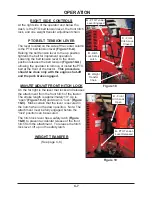
Page 12: ...y for open area operation where travel speed and direction is relatively constant and control is very easy to maintain Easy shift mode reduces operator arm fatigue see Figure 49 for 3 position decal HIGH LOW RANGE HIGH LOW transaxle shift lever Shown in Figure 5 Forward is LOW range Back is HIGH range NEVER SHIFT WHILE UNDER LOAD MOVING OR ON A SLOPE The shift lever shifts both transaxles simultan...

Page 13: ...s important to avoid unexpected and difficult situations that could cause serious injury or damage to operator or equipment See safety section II The second function of the primary lever controls the hydraulic front hitch Pulling the lever to the left toward the operator raises the hitch Moving it to the first position to the right is to lower front hitch with down pressure Second position to the ...

Page 14: ...r If a manual is missing contact the dealer for replacement The left fender houses the 7 25 gallon fuel tank Always note the type of fuel Unleaded Gasoline or Diesel Figure 9 If decal is missing or unreadable contact your dealer for a replacement decal Determine fuel type before ordering Never over fill Stop before fuel spills over the fill opening A long slot in the left fender at the front insid...

Page 15: ...t be seated to activate the front PTO They are there for your protection The roll bar Figure 14 is mounted with four 3 8 x 1 grade 5 hex bolts with 3 8 SF nuts on each side Torque to 30 FT LBS Note Roll bar mounting flange is on the inside of fender panel All VENTRAC 4200s are shipped with roll bar and hardware Roll bar maybe furnished unmounted for shipping convenience Roll bar must be installed ...

Page 16: ...erent settings Figure 16 Note the three positions under the left front corner of the foot platform Factory setting uses the inside hole Dual wheels require the middle hole setting The weather cab and loader require the outside hole setting The outer settings reduce the turning radius This prevents tire and frame interference COUNTER WEIGHTS Four 42 pound counter weights are standard equipment on t...

Page 17: ...ne only with the engine shut off and the park brake engaged MINUTE MOUNT FRONT HITCH LOCK On the far right is the lever that locks and releases the attachment from the front hitch of the tractor The stroke length is approximately 10 Up is open Figure 19 C and down is lock Figure 18 C Make certain that the lever is secured in the notch when in the down position Note The attachment must be fully eng...

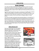
Page 18: ...es of this system are increased traction to the drive wheels increased lifting capacity and it allows the attachment to float over the surface contours with less weight in contact with the ground This is a valuable feature when using the mower snow thrower slip scoop leaf blower and other attachments On the lower right hand side of the dash is a weight transfer chain See pg C 7 Figure 18 B This ch...

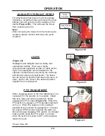
Page 19: ...engaging the PTO switch Figure 23 When the PTO switch is engaged a PTO operation light will come on When the engine is cold stalling is possible at the moment of engagement Increase the engine RPM s and or increase the warm up time and repeat engaging PTO switch An integral brake system stops the PTO within 7 seconds when the switch is moved to OFF or the operator leaves the seat Power Take Off PT...

Page 20: ...ry Figure 24 7 Diesel models turn the key clockwise to the first detent and wait until the glow plug light goes off 8 Turn the key clockwise Figure 25 until the engine starts 9 Once the tractor is started let the engine and transmission system warm up a minute or two Always check to see if the steering system is responsive before attempting to drive the tractor This assures that the hydraulic syst...

Page 21: ...and push it into the tractor as far as the hitch will allow Make sure both sides are against the stop 3 Place the mower PTO belt over the outside groove of the idler pulley 4 Return to the tractor seat Engage the Minute Mount lever into the latched position and rotate the PTO tension lever up into the engaged position Note 1 Mower attachments have a floating hitch Figure 26 27 If mower cutting hei...

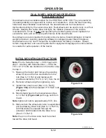
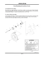
Page 22: ...Note the pin on the draw cone must be turned toward the draw bolt head DUAL WHEEL MOUNTING OPERATION KTA LATE STYLE Dual wheels are an available option for the VENTRAC 4200 VXD They are useful for increasing stability on slopes and to reduce soil compaction Once the dual mounting hubs have been installed in each wheel the dual wheels can be mounted and dismounted quickly by the center draw bolt Du...

Page 23: ...e inner wheel mount turn wheel clockwise until the wheel is hand tight Using a 1 socket torque draw bolt to 120 ft Lbs To remove wheel assembly Loosen draw bolt See C 13 Ref 10 approximately 5 turns and hit the end of the draw bolt sharply with a medium size hammer This will loosen the draw cone and allow removal of the dual assembly by turning counter clockwise 00 0202 REVISED 05 16 05 ...

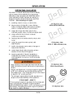
Page 24: ...opes decreases tractor stability and increases the possibility for unexpected difficulties Only experienced VENTRAC 4200 VXD operators should operate the tractor on slopes and extra caution should be used that includes See drawings at right 1 avoiding uneven loose or wet terrain 2 staying clear of drop offs holes ditches rocks or objects that could cause a sudden and or unexpected force on the tra...

Page 25: ...al problems Personal safety and the safety of others as well as the performance of the equipment depend on the operator s care and repair of the machine and continuous caution and control of the same Lubrication Grease the center pivot and the front hitch pivot at the grease zerks at engine oil and filter change Grease fittings on lift and steering cylinders if a fitting is provided Engine Oil and...

Page 26: ...igure 34 It requires an 11 16 wrench Oil stream will be directed nearly straight down Overflow bottle Engine Oil Drain RADIATOR The fluid or coolant level can be checked visually in the overflow bottle Figure 35 Vanguard turbo diesel shown Full and low marks are shown on the plastic bottle If low a 50 50 mixture of water and antifreeze should be added Check the radiator core for debris Keep screen...

Page 27: ...mmend oiling the foam prefilter outer element Expansion tank HYDROSTATIC TRANSMISSION OIL The top oil reservoir for the hydrostatic transmission oil is located under the hood near the right side of the dash Check oil level when engine is cold Find the oil level in the plastic sight tube next to the expansion tank and check that it is within the proper range indicated by the oil level decal This is...

Page 28: ...ansaxle Oil can be added through the plug from the rear Figure 38 It is located above the rear hitch and slightly to the left To check the oil level on a level surface remove the oil fill plug in the transaxle Figure 38 and check to see if oil level is even with the bottom of oil fill hole If no rear transaxle leaks are observed this level should be checked every 250 hours or annually Oil fill plu...

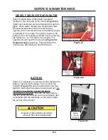
Page 29: ...change both filters Replacement of oil filters may create some oil spill A shallow pan or towel can be helpful in containing the oil spill Pressure Filter Inline Fuel Filter Suction Filter FUEL LINE FILTER S IN LINE FUEL FILTER All VENTRAC 4200 VXD s have an in line fuel filter Figure 42 located inside the foot platform cover near engine on Kawasaki models Always use clean fresh fuel Keep the fill...

Page 30: ...nds The operator should hear the fuel pump Figure 44 Vanguard only operating Purging should be done before attempting to start the tractor Electric Fuel pump Filter Water Separator BATTERY When it is necessary to remove and or replace the battery remove both cables Then remove the bracket Figure 45 near the left side of the foot platform and slide the battery forward and out To install the new bat...

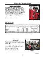
Page 31: ... lock nut clockwise several turns Check if sufficient pressure is applied for brake to hold Adjust lock nut until the brake hold is firm If the brake adjustment is too tight it will be difficult to engage the control selector into the park position Brake Adjustment Fuse Block ELECTRICAL Fuses and relays are conveniently located just under the dash and accessible with the hood open Figure 48 See wi...

Page 32: ...he nut just enough to free the grip of the bolt from the slot Move the bolt slightly in either direction until the tendency to creep stops Retighten the bolt NOTE The neutral adjustment procedure is recommended with the engine running around 2000 RPMs NOTE If in doubt about this procedure or your efforts fail to remedy the problem contact your VENTRAC dealer Figure 50 Neutral Adjustment Bolt Cauti...

Page 33: ...equire steps 2 3 6 and 7 Steps 1 7 for Vanguard engines 1 Remove belt from lower PTO idler pulley 2 Remove nut from bottom flange on front grille torque rod Figure 52 3 Disconnect the 2 wire plug to clutch assembly on service cord about 6 to 10 inches from clutch assembly 4 Remove belt 5 Replace with new belt B38 by reversing the procedure 6 Reconnect 2 wire plug to clutch 7 Reinstall spring and n...

Page 34: ...E 1 WIRING DIAGRAM 01 27 05 ...

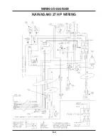
Page 35: ...E 2 WIRING DIAGRAM KAWASAKI 27 HP WIRING ...

Page 36: ...E 3 WIRING DIAGRAM VANGUARD GAS WIRING ...

Page 37: ...E 4 WIRING DIAGRAM VANGUARD DIESEL WIRING ...

Page 38: ...e If this warranty covers a product used commercially or for any income producing purpose the foregoing warranties are in lieu of all other warranties and no representations guarantees or warranties express or implied including but not limited to a warranty of merchantability or fitness for a particular purpose are made by V P I in connection with the manufacture or sale of its products The engine...

Page 39: ...similar replacement equipment during the period of any warranty repair or replacement work v any telephone or telegram charges vi loss or damage to person or property other than that covered by the terms of this warranty vii any claims for lost revenue lost profit or additional cost or expense incurred as a result of a claim of breach of warranty or viii attorney s fees The remedies of buyer set f...

Reviews: