Operation - 15
EDGER SETUP & CONFIGURATION
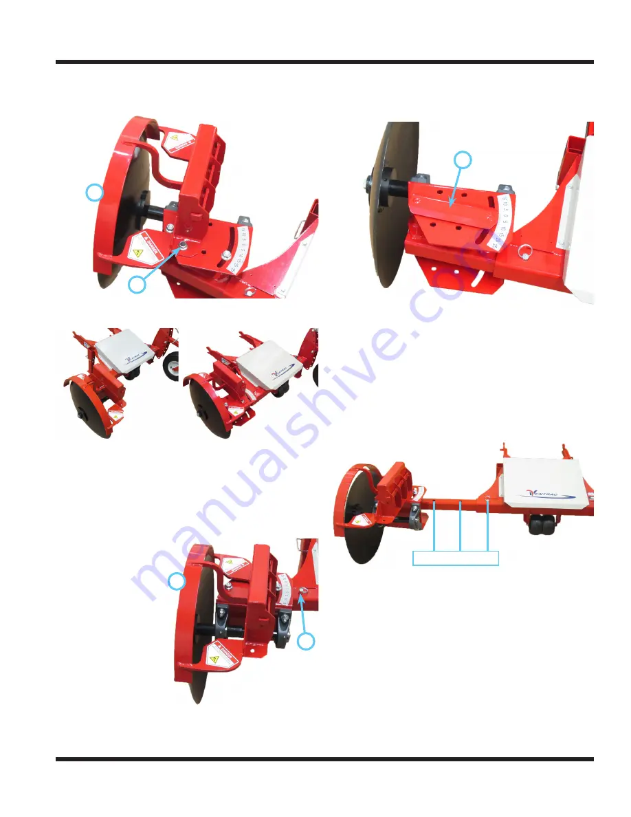
6. Reinstall the disc guard (A) onto the bearing
mount plate using the outer set of holes (B) to
position the guard over the edge of the disc.
A
B
Disc Position Setup
The edger disc can be positioned either in front of or
behind the main frame receiver tube. NOTE: if the
edger is equipped with an optional blower kit, posi-
tioning the disc behind the main frame receiver tube
will block the airflow and prevent debris from being
blown away from the edge.
To change the position of the disc:
1. Remove the
A
B
disc guard (A)
from the bearing
mount frame by
removing the 1/2”
nuts and washers
from the disc
guard clamp.
2. Remove the ball
pin (B) from the
frame receiver
tube, remove
the disc frame
assembly from
the main frame receiver tube, and rotate the disc
frame assembly 180 degrees.
3. With the disc positioned on the desired side of
the main frame receiver tube, reinsert the disc
frame tube into the main frame receiver tube,
and secure with the ball pin.
4.
C
Remove the disc adjust lock clamp (C) from the
top of the bearing mount frame and reinstall
the clamp and washers from the bottom and up
through the bearing mount frame and disc frame
clamp tubes. Secure with the 1/2” flat washers
and flange nuts.
5. Reinstall the disc guard onto the bearing mount
frame in position to cover the top edge of the disc.
Disc Edger Extension
Normal 6” 12”
The disc mount frame tube has three mounting
positions. The normal mounting position locates the
edger disc closest to the main frame. This position
should be used whenever possible. The disc frame
also can be extended either 6 inches (15.2 cm) or
12 inches (30.5 cm) to reach over curbs or into hard
to reach areas.
1. Remove the ball pin from the frame receiver
tube, slide the disc mount frame tube out to the
desired position, and secure with the ball pin.
2. After edging of area that requires the edger
disc to be extended is complete, return the disc
mount frame tube to the normal position.


