GENERAL OPERATION
Operation - 18
switch to active the fan. Drive forward slowly while
continuing to lower the edger until the tire touches
the ground. Move the SDLA lever to the float posi
-
tion and maintain a speed that allows the operator
to control the edger. Guide the edger disc along the
edge of the sidewalk or other edging area. At the end
of the edging line, decrease the power unit speed
and lift the edger out of the ground. If equipped with
a blower option, shut off the PTO switch.
Do not make sharp turns with the disc in the ground.
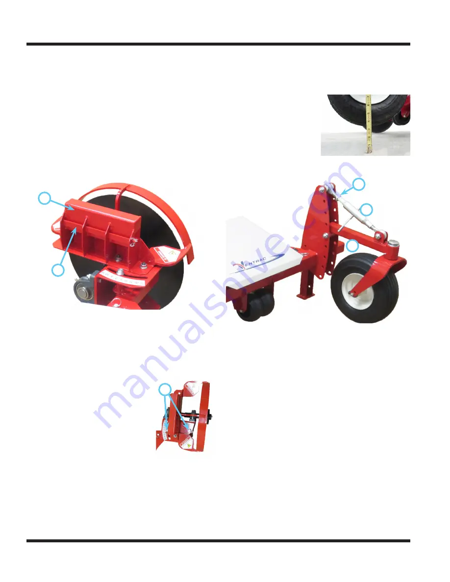
If the edger will not cut to the desired depth, weight
must be added. The weight bar bracket (A) on the
disc guard frame will accomodate three Ventrac
weights (part # 47.0115).
A
B
Remove the weight retainer pin and install the
weights onto the weight bar. Reinstall the weight
retainer pin and secure with the hair pin.
Edger Disc Angle Adjustment
The disc angle can be changed to create a wider or
narrower edging line. To change the disc angle:
1. Loosen the two 1/2” nuts (A) on
A
top of the bearing mount frame.
2. Rotate the edger disc to the
desired angle. The decal on the
bearing mount frame is useful
for setting a desired angle or for
measuring small incremental
adjustments to the disc angle.
3. Retighten the 1/2” nuts to lock
the disc angle.
Edger Cutting Depth Adjustment
1. Park the power unit and edger on a level sur-
face, preferably concrete or asphalt.
2. Lower the edger until the edger disc just touches
the surface.
3. Measure the distance
between the surface
and the bottom of the
tire to determine the
approximate edging
depth.
4. If the cutting depth needs to be adjusted, loosen
the locking nut (A) on the adjustable link (B).
5.
B
A
C
Turn the adjustable link until the measurement
between the surface and the bottom of the tire
reaches the desired depth. For a shallower cut,
lengthen the adjusting link. For a deeper cut,
shorten the adjusting link.
6. When the desired depth is reached, tighten the
locking nut against the body of the adjustment link.
NOTE: the gauge wheel arm (C) should be as near
level as possible. Move the gauge wheel arm and
the adjusting link up or down in the series of holes
in the gauge wheel frame in order to maintain a near
level position.


