background image

Revised 03/09/16 

09.10097 Rev. 02

Original Operator’s Manual

M

odel

 lM600 M

ower

e

urope


S

erial

 N

uMber

 lM600-bb1569 --

o

perator

S

 M

aNual

& p

artS

 d

rawiNgS

Summary of Contents for LM600

Page 1: ...Revised 03 09 16 09 10097 Rev 02 Original Operator s Manual Model LM600 Mower Europe Serial Number LM600 BB1569 Operator s Manual Parts Drawings ...

Page 2: ..._______________________ Dealer ____________________________________________________________________________ Dealer Address _____________________________________________________________________ _____________________________________________________________________ Dealer Phone Number _______________________________________________________________ Dealer Fax Number ___________________________________...

Page 3: ...tting Unit Safety 14 OPERATIONAL CONTROLS PAGE 15 Operational Control Locations 15 Main Belt Tensioner A 15 Height Adjustment Handle B 15 GENERAL OPERATION PAGE 16 Daily Inspection 16 Attaching 16 Detaching 16 Mowing and Operating Procedure 16 Transport of Mower 17 Cutting Height Adjustment 17 SERVICE PAGE 18 Cleaning and General Maintenance 18 Deck Flip Up Procedure Service Position 18 Mower Blad...

Page 4: ...FICATIONS PAGE 22 Dimensions 22 Features 22 Noise Emissions 23 EC Declaration of Conformity 23 PARTS PAGE 24 Main Deck 24 Carrier Frame 26 Front Caster Wheels Rear Roller 28 Hitch Assembly 30 Spindles Blades 32 WARRANTY PAGE 34 ...

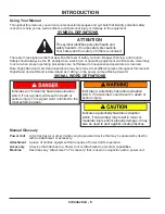
Page 5: ... divided into sections for convenient reference of the appropriate section You must read and understand the operator s manual for each piece of Ventrac equipment you own Read ing the operator s manual will help you become familiar with each specific piece of equipment Under standing the operator s manual will help you as well as others avoid personal injury and or damage to the equipment Keep this...

Page 6: ...ughout this manual Right Hand and Left Hand is determined as if sitting on the power unit seat facing forward SIGNAL WORD DEFINITIONS Indicates a potentially hazardous situation which if not avoided could result in death or serious injury Indicates an imminently hazardous situation which if not avoided will result in death or serious injury This signal word is limited to the most extreme cases Ind...

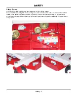
Page 7: ...fety decals legible Remove all grease dirt and debris from safety decals and instructional labels If any decals are faded illegible or missing contact your dealer promptly for replacements When new components are installed be sure that current safety decals are affixed to the replacement components A B C E D D F D F ...

Page 8: ...ories Decal Description Part Number Quantity A Danger Shield Missing 00 0062 1 B Warning Moving Part Hazard 00 0101 1 C Danger Pinching Hazard 00 0102 1 D Danger Keep Hands Feet Clear 00 0123 3 E Warning Read Owner s Manual 00 0217 1 F Danger Thrown Object Hazard 00 0265 2 A B C D E F ...

Page 9: ...g parts Be sure guards and shields are in proper working condition and are secured in place Make all necessary adjustments before operating machine Some pictures in this manual may show shields or covers opened or removed in order to clearly illustrate any instructions Under no circumstance should the machine be operated without these devices in place Alterations or modifications to this machine c...

Page 10: ...ion Do not run the engine in a building without adequate ventilation Do not touch the engine or the muffler while the engine is running or immediately after stopping the engine These areas may be hot enough to cause a burn Do not change the engine governor settings or over speed the engine Operating engine at excessive speed may increase the hazard of personal injury To reduce the hazard of fire k...

Page 11: ...und to improve stability While operating on slopes drive in an up and down direction when possible If turning is necessary while driving across slopes reduce speed and turn slowly in the downhill direction Assure a sufficient supply of fuel for continuous operation A minimum of one half tank of fuel is recommended Roadway Safety Operate with safety lights when operating on or near roadways Obey al...

Page 12: ...mponents while the engine is running or imme diately after stopping the engine These areas may be hot enough to cause a burn Allow the engine to cool before storing and do not store near an open flame Do not change the engine governor settings or over speed the engine Operating engine at excessive speed may increase the hazard of personal injury Springs may contain stored energy Use caution when d...

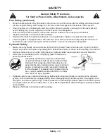
Page 13: ... tubes are in good condition Repair any leaks and replace any damaged or deteriorated hoses or tubes before starting the machine Hydraulic leaks can occur under high pressure Hydraulic leaks require special care and attention Use a piece of cardboard and a magnifying glass to locate sus pected hydraulic leaks Keep body and hands away from pinhole leaks or nozzles that eject high pressure hydraulic...

Page 14: ... personal injury Keep hands and feet away Rotation of one blade may cause another blade to rotate Thrown Object Hazard Do not point discharge toward people animals or buildings when operating Never operate with the deflectors removed When not mowing always shut off the PTO to stop the mower blades Never raise the mower deck with the blades running ...

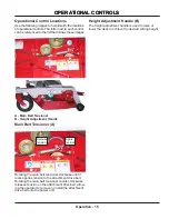
Page 15: ... Adjustment Handle Main Belt Tensioner A Release tension Apply tension Rotating the main belt tensioner clockwise until it locks applies tension to the attachment drive belt Rotating the main belt tensioner counter clockwise releases tension on the attachment drive belt allow ing the operator to remove or install the attachment drive belt onto the power unit Height Adjustment Handle B The height a...

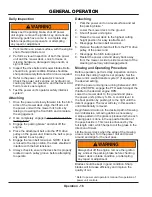
Page 16: ...attempting to operate Detaching 1 Park the power unit on a level surface and set the parking brake 2 Lower the mower deck to the ground 3 Shut off power unit engine 4 Raise the mower deck to the highest cutting height position for easy reattachment 5 Disengage the main belt tensioner 6 Remove the attachment belt from the PTO drive pulley of the power unit 7 Disengage the hitch locking lever 8 Rest...

Page 17: ...faces to maintain control of power unit and to reduce the shock to the power unit and mower deck Always disengage the power unit PTO before transporting the mower Cutting Height Adjustment 1 Always shut off the engine remove the ignition key and set the parking brake before checking mower deck or blade condition or attempting any repair or adjustment Lift the height adjustment handle upward and ho...

Page 18: ...install the ball pins and lower the mower deck shield into place Mower Blade Removal Installation 1 Mower blades may be sharp Always wear safety glasses leather gloves and a long sleeve shirt when working with mower blades Rotate the mower deck up to the service posi tion following the deck flip up procedure 2 Place a short piece of 2 x 4 wood between the end of the blade and an appropriate struct...

Page 19: ...ping or crushing a bodily appendage 4 Check the mower blades to ensure they are not bent To check for bent blades move one blade tip to the back of the deck and measure from the floor to the blade Rotate the other blade tip to the back of the deck and measure again If the distance is different the blade is bent and should be replaced before continuing 5 Go to one side of the deck Turn the blade so...

Page 20: ...ing the Mower for Storage 1 Clean the mower deck and frame 2 Inspect for loose or missing hardware damaged components or signs of wear Repair or replace any damaged or worn components 3 Inspect belts spindles and blades Repair or replace any damaged or worn components 4 Inspect safety decals Replace any safety decals that are faded illegible or missing 5 Apply grease to all grease points 6 Wipe of...

Page 21: ...Inspect Belts Pulleys Blades and Blade Retaining Bolts Grease Lubrication See Lubrication Section Inspection Maintenance Checklist Maintenance Checklist o f L o c a t i o n s o f P u m p s A S N E E D E D D a i l y A t 5 0 H o u r s A t 1 0 0 H o u r s A t 1 5 0 H o u r s A t 2 0 0 H o u r s A t 2 5 0 H o u r s A t 3 0 0 H o u r s A t 3 5 0 H o u r s A t 4 0 0 H o u r s A t 4 5 0 H o u r s A t 5 0...

Page 22: ... Overall Width 70 inches 178 cm Weight 310 pounds 141 kg Cutting Width 60 inches 152 cm Approximate Cutting Height Range 1 1 2 3 3 4 inches 3 8 9 5 cm Number of Cutting Positions 10 positions Number of Blades 3 blades Features Flip up Deck Single Lever Linear Adjustment System Field Serviceable Spindles Full Floating Deck ...

Page 23: ...r Manufacturer Venture Products Inc 500 Venture Drive Orrville OH 44667 USA Authorized Representative also authorized to compile the technical file Lars Persson LAPAB MASKIN AB Box 46 S 734 22 Hallstahammar Flädervägen 5 734 38 Hallstahammar SWEDEN Technical File Keeper Ryan Steiner Venture Products Inc 500 Venture Drive Orrville OH 44667 USA Description Finish mowing attachment Model Name Ventrac...

Page 24: ...Illustrated Parts 24 Use only original Ventrac replacement parts ILLUSTRATED DRAWING Main Deck PARTS ...

Page 25: ... 16 18 USS 1 15 03 0006 PIN BALL 3 8 X 1 2 16 00 0123 DECAL KEEP HANDS FEET CLEAR 3 17 90 0414 BOLT 1 4 20 USS X 1 3 4 1 18 99 SF04 NUT SRF 1 4 20 USS 2 19 97 0506 BOLT CARRIAGE 5 16 X 3 4 14 20 62 0867 FRAME TOP DECK PLATE 1 21 99 SF05 NUT SRF 5 16 18 USS 14 22 60 1056 COVER PULLEY 1 23 99 SF06 NUT SRF 3 8 16 USS 6 24 00 0062 DECAL DANGER SHIELD MISSING 1 25 62 0866 DECK MAIN WELDMENT 1 26 99 SF0...

Page 26: ...PARTS Illustrated Parts 26 Use only original Ventrac replacement parts ILLUSTRATED DRAWING Carrier Frame ...

Page 27: ... 90 0612 BOLT 3 8 16 USS X 1 1 2 5 16 99 SF05 NUT SRF 5 16 18 USS 2 17 93 06 NUT 3 8 24 SAE 4 18 99 J0620NF ROD THREADED 3 8 24 X 2 1 2L 2 19 90 0514 BOLT 5 16 18 USS X 1 3 4 2 20 42 0425 SHAFT HEIGHT ADJUST CROSSBAR 1 21 99 A06 LOCKNUT STOVER 3 8 16 USS 5 22 41 0039 SPRING COMP 9 16 OD X 5 8 1 23 64 0795 BRACKET HT SETTING CONTROL 1 24 64 0799 BUSHING PIPE 1 4 X 1 1 8L 2 25 95 06 WASHER FLAT 3 8 ...

Page 28: ...PARTS Illustrated Parts 28 Use only original Ventrac replacement parts ILLUSTRATED DRAWING Front Caster Wheels Rear Roller ...

Page 29: ... 8 16 USS X 5 1 2 2 11 50 0185 SPINDLE TIRE SWIVEL 9 2 12 04 0025 SNAP RING EXT 1 SHFT 078 THK 2 13 64 0893 BUSHING ROLLER LM600 2 14 50 0056 ROLLER END 4 OD X 2 69 LONG 2 15 95 16 WASHER FLAT 1 SAE A R 16 80 0292 ROLLER REAR 1 17 99 SF05 NUT SRF 5 16 18 USS 4 18 55 FB16016 BEARING FLANGE BLOCK 1 REGGF 2 19 99 SF0508 BOLT SRF 5 16 18 USS X 1 4 20 95 12 WASHER FLAT 3 4 SAE A R 21 29 GF0001 GREASE F...

Page 30: ...PARTS Illustrated Parts 30 Use only original Ventrac replacement parts ILLUSTRATED DRAWING Hitch Assembly ...

Page 31: ... 0 438 X 0 875 1 10 83 0037 PULLEY IDLER FLAT 4 X 3 8 2 11 60 0726 BRACKET IDLER BELT RETAINER 2 12 95 06 WASHER FLAT 3 8 SAE 10 13 90 0614 BOLT 3 8 16 USS X 1 3 4 2 14 90 0622 BOLT 3 8 16 USS X 2 3 4 1 15 99 A06 LOCKNUT STOVER 3 8 16 USS 3 16 00 0101 DECAL HAZARD MOVING PART 1 17 99 SF06 NUT SRF 3 8 16 USS 1 18 41 0048 SPRING EXT 1 OD X 6 1 19 90 0610 BOLT 3 8 16 USS X 1 1 4 1 20 00 0102 DECAL DA...

Page 32: ...PARTS Illustrated Parts 32 Use only original Ventrac replacement parts ILLUSTRATED DRAWING Spindles Blades ...

Page 33: ...RH 25MM AL 3 8 99 E0082 NUT LOCKING FLANGE 3 8 16 12 9 99 B0091 WASHER 510 ID X 2 1 2 OD 1 4 6 10 79 0051 BLADE 20 50X1 2 RH S MULCH 3 11 64 0688 GUARD SPINDLE STRING WRAPPER 3 12 91 0816 8 BOLT 1 2 20 X 2 GR8 3 13 60 0768 BRACKET BELT RETAINER 2 31 29 GF0001 GREASE FTG 1 4 SAE ST 1 32 55 0057 BEARING BALL 25 MM X 62 MM 2 33 87 0209 2 SHAFT SPINDLE RH 1 34 85 W0406 KEY WOODRUFF 1 4 X 3 4 1 35 87 0...

Page 34: ...s or implied including but not limited to a warranty of merchantability or fitness for a particular purpose are made by V P I in connection with the manufacture or sale of its products The engine warranty is covered by its respective engine manufacturer Please refer to the engine manufacturer s war ranty statement that is included in the owner s manual The Ventrac turf equipment including any defe...

Page 35: ...is warranty vii any claims for lost revenue lost profit or additional cost or expense incurred as a result of a claim of breach of war ranty or viii attorney s fees The remedies of buyer set forth herein are exclusive and are in lieu of all other remedies The liability of V P I whether in contract tort under any warranty or otherwise shall not extend beyond its obligation as set forth herein V P I...

Reviews: