background image

O

PERATOR

S

 M

ANUAL

& P

ARTS

 D

RAWINGS

R

EAR

 D

ISCHARGE

 M

OWER

M

ODEL

 MC600

Revised 04/17/14

09.10056 Rev. 02

Original Operator’s Manual

Summary of Contents for MC600

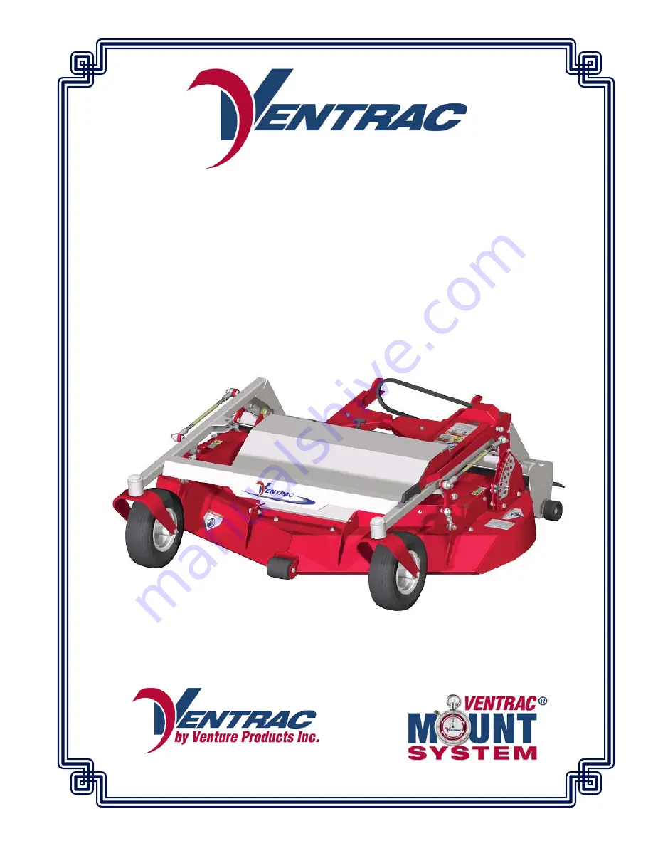
Page 1: ...OPERATOR S MANUAL PARTS DRAWINGS REAR DISCHARGE MOWER MODEL MC600 Revised 04 17 14 09 10056 Rev 02 Original Operator s Manual ...

Page 2: ...______________________________________________________________ Dealer Address _________________________________________________________ __________________________________________________________ Dealer Phone Number ___________________________________________________ Dealer Fax Number _____________________________________________________ Model A _____________________ Serial B _____________________ ...

Page 3: ...iders Off 10 Operating On Slopes 11 Roadway Safety 11 Truck Or Trailer Transport 11 Maintenance 12 Fuel Safety 12 Hydraulic Safety 13 Cutting Unit Safety 14 OPERATIONAL CONTROLS PAGE 15 Height Adjustment Handle 15 Height Adjustment Locking Pin 15 Deck Pivot Latch 15 S D L A Control Levers 15 Weight Transfer 15 GENERAL OPERATION PAGE 16 Daily Inspection 16 Attaching 16 Detaching 16 Mowing and Opera...

Page 4: ...stments 19 Tire Pressure 19 Deck Leveling Procedure 19 Lubrication 20 MC600 Maintenance Schedule 21 MC600 Maintenance Checklist 21 SPECIFICATIONS PAGE 22 Dimensions 22 Features 22 PARTS PAGE 24 Deck Pulleys Belt 24 Spindles Blades 26 Hitch Arms 28 Carrier Frame Wheels Front Roller 30 Deck Shields 32 Rear Roller 34 Rear Belting 36 Rear Crossbar 38 Left Height Adjustment Linkage 40 Right Height Adju...

Page 5: ...hers avoid personal injury and or damage to the equipment Keep this manual with the machine at all times The manual should remain with the machine even if it is sold If this manual becomes damaged or unreadable it should be replaced immediately Con tact your local Ventrac dealer for a replacement When using a Ventrac attachment be sure to read and follow the safety and operating instructions of bo...

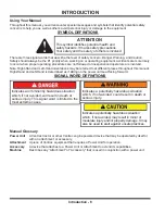
Page 6: ...ughout this manual Right Hand and Left Hand is determined as if sitting on the power unit seat facing forward SIGNAL WORD DEFINITIONS Indicates a potentially hazardous situation which if not avoided could result in death or serious injury Indicates an imminently hazardous situation which if not avoided will result in death or serious injury This signal word is limited to the most extreme cases Ind...

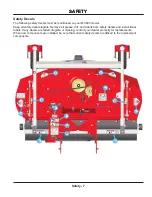
Page 7: ...ed on your MC600 mower Keep all safety decals legible Remove all grease dirt and debris from safety decals and instructional labels If any decals are faded illegible or missing contact your dealer promptly for replacements When new components are installed be sure that current safety decals are affixed to the replacement components ...

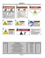
Page 8: ...B Warning Moving Part Hazard 00 0101 1 C Danger Keep Hands Feet Away 00 0123 4 D Warning Pinch Point 00 0218 2 E Warning Do Not Reach 00 0219 1 F Warning Read Owner s Manual 00 0217 1 G Warning General Safety 00 0220 1 H Danger Thrown Object Hazard 00 0265 2 A A B B C C D D E E F F G G H H ...

Page 9: ...rn or missing parts Be sure guards and shields are in proper working condition and are secured in place Make all necessary adjustments before operating machine Some pictures in this manual may show shields or covers opened or removed in order to clearly illustrate any instructions Under no circumstance should the machine be operated without these devices in place Alterations or modifications to th...

Page 10: ... not run the engine in a building without adequate ventilation Do not touch the engine or the muffler while the engine is running or immediately after stopping the engine These areas may be hot enough to cause a burn Do not change the engine governor settings or over speed the engine Operating engine at excessive speed may increase the hazard of personal injury To reduce the hazard of fire keep th...

Page 11: ...n safely be controlled on slopes Transport machine with attachment lowered or close to the ground to improve stability While operating on slopes drive in an up and down direction when possible If turning is necessary while driving across slopes reduce speed and turn slowly in the downhill direction Assure a sufficient supply of fuel for continuous operation A minimum of one half tank of fuel is re...

Page 12: ... enough to cause a burn Do not change the engine governor settings or over speed the engine Operating engine at excessive speed may increase the hazard of personal injury Springs may contain stored energy Use caution when disengaging or removing springs and or spring loaded components An obstruction or blockage in a drive system or moving rotating parts may cause a buildup of stored energy When th...

Page 13: ...from pinhole leaks or nozzles that eject high pressure hydraulic fluid Hydraulic fluid escaping under high pres sure can penetrate the skin causing serious injury If hydraulic fluid is injected into skin seek immediate medical attention Hydraulic system may contain stored energy Before performing maintenance or repairs on the hydraulic system remove attachments engage parking brake disengage weigh...

Page 14: ... injury Keep hands and feet away Rotation of one blade may cause another blade to rotate Thrown Object Hazard Do not point discharge toward people animals or buildings when operating Never operate with the deflectors removed When not mowing always shut off the PTO to stop the mower blades ti ti ti t t ti ti i i i ti t t t t t ti t t ti t ti i i i i i i i i ...

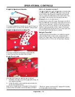
Page 15: ...the right side of the seat The primary lever controls the speed and direction of the power unit as well as the lift function of the front hitch The secondary lever controls the auxiliary hydraulics Primary S D L A Control Lever Pull the lever to the left to raise the power unit front hitch and MC600 mower deck Push the lever to the right to lower the power unit front hitch and mower deck The contr...

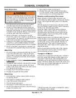
Page 16: ...ower to the ground Shut off power unit engine Disengage the PTO belt tensioning lever Remove the attachment belt from the PTO drive pulley of the power unit 1 2 3 4 5 1 2 3 4 5 6 1 2 3 4 5 6 Open the front hitch locking lever Restart the power unit and slowly back away from the mower A side to side movement of the steering wheel may aid disengagement Mowing and Operating Procedure Before operation...

Page 17: ...cutting height and replace the height adjustment locking pin Slide the height adjustment handle towards the rear of the deck until it is free of the height adjustment lift rocker and then rotate down to lay flat along the carrier frame Mulching Kit 70 8088 Optional Accessory Mulching procedures may vary greatly due to cli mate type of grass and soil conditions It is gener ally best to mow frequent...

Page 18: ...wer Blade Inspection Replacement Mower blades may be sharp Always wear heavy gloves when working with mower blades Rotate the mower deck up to the service position following the deck flip up procedure Inspect the mower blades to ensure cutting edges are sharp If blades are dull or damaged they must be removed and sharpened or replaced Place a short piece of 2 x 4 wood between the end of the blade ...

Page 19: ...ard surface that is clean and level Place the height adjustment pin in the normal cutting height position ie If the deck is usually set at 2 51mm to mow set it at 2 51 mm to level the deck Ensure both front tires are inflated to the recom mended tire pressure See Tire Pressure section 1 2 3 4 1 2 3 4 5 6 1 2 3 Check the mower blades to ensure they are not bent Starting at either side of the deck t...

Page 20: ...e shown on a decal located on the under side of the deck shield Storage Preparing the MC600 Mower for Storage 1 Clean the mower deck and frame 2 Inspect for loose or missing hardware damaged components or signs of wear 3 Inspect hydraulic hoses and fittings if equipped to ensure tight leak free connections Repair or replace any damaged or worn components 4 Inspect belts spindles and blades Repair ...

Page 21: ...SERVICE Service 21 MC600 Maintenance Schedule MC600 Maintenance Checklist ...

Page 22: ...ting Width 58 inches 147 3 cm Weight 420 pounds 190 5 kg Blade Length 20 1 2 inches 52 cm Cutting Height Range 3 4 1 9 cm Min to 4 1 2 11 4 Max Cutting Height Adjustment Increments every 1 4 64 cm Front Wheels Pneumatic Rear Roller Full Width Smooth Anti scalp Roller Adjustable 2 position Features Flip up Deck Design Rear Discharge Center Front Roller for Anti scalping Full Rear Roller for Even Cu...

Page 23: ...Blank Page ...

Page 24: ...WING Deck Pulleys Belt PARTS 21 8 8 8 8 8 8 8 8 8 8 8 8 15 15 7 9 24 22 22 22 6 6 6 6 6 6 6 6 6 6 6 6 6 10 10 4 13 18 18 17 5 5 19 20 2 1 12 12 12 12 16 14 14 20 12 3 15 14 12 13 20 13 6 3 3 4 23 22 9 11 25 5 19 26 27 27 26 27 7 Serial 1001 1151 Serial 1001 1151 7 5 4 7 5 5 5 5 6 4 ...

Page 25: ...E0076 NUT JAM 5 8 11 USS 2 11 90 1048 BOLT 5 8 11 UNC X 6 1 12 64 1445 BUSHING 1 ID X 1 5 OD X 1 L 6 13 83 0056 PULLEY 6 1 2 25MM STR BORE 3 14 99 B0096 WASHER 328IDX1 625ODX 188THK 3 15 90 0508 BOLT HEX 5 16 18 UNC X 1 3 16 81 B162 BELT B162 1 17 41 0065 SPRING DOUBLE TORSION BLACK 1 18 04 0007 RIVET POP DOME 1 8 X 1 8 S S 2 19 95 10 WASHER FLAT 5 8 SAE 2 20 96 05 WASHER LOCK 5 16 3 21 99 SF0404 ...

Page 26: ...inal Ventrac replacement parts ILLUSTRATED DRAWING Spindles Blades 9 9 9 9 9 9 6 8 8 8 8 8 8 8 8 8 8 7 7 7 7 7 7 7 7 7 5 8 8 8 8 8 8 8 8 2 2 1 2 1 1 6 5 4 9 9 9 9 7 7 7 7 3 3 4 5 4 7 7 9 9 9 9 3 9 9 9 9 7 7 7 87 0224 6 11 11 10 13 16 12 15 14 ...

Page 27: ...ING 3 5 99 B0097 WASHER 635ID X 2 1 2OD X 1 4 3 6 91 1014 BOLT 5 8 18 SAE X 1 3 4 3 7 95 06 WASHER FLAT 3 8 SAE 18 8 99 E0082 NUT LOCKING FLANGE 3 8 16 18 9 90 0612 BOLT 3 8 16 USS X 1 1 2 18 10 87 0224 1 HOUSING SPINDLE 1 11 55 0070 BEARING 30MM X 62MM X 16MM 2 12 87 0224 2 SHAFT SPINDLE 1 13 87 0224 3 SHIELD BOTTOM 1 14 29 GF0001 GREASE FTG 1 4 SAE ST 1 15 29 GF0017 RELIEF FITTING 1 16 87 0224 4...

Page 28: ...y original Ventrac replacement parts ILLUSTRATED DRAWING Hitch Arms 23 8 16 16 27 29 21 6 11 26 25 9 9 9 30 24 24 28 28 22 22 13 14 15 15 20 20 2 19 16 16 12 8 6 6 7 21 8 8 16 11 10 9 12 27 31 4 3 5 9 30 9 18 1 16 35 34 33 32 23 17 7 6 ...

Page 29: ...Y 6 H BUSH 1 15 05 0095 BUMPER RUBBER CYLINDRICAL 2 16 90 0406 BOLT 1 4 20 USS X 3 4 6 17 81 B047 BELT B47 1 18 42 0450 LINK SPACING LIFT ARMS 1 19 60 1044 SHIELD DRIVE PULLEY 1 20 95 10 WASHER FLAT 5 8 SAE 2 21 90 1018 BOLT 5 8 11 USS X 2 1 4 2 22 99 A10 LOCKNUT STOVER 5 8 11 USS 2 23 99 SF0506 BOLT SF 5 16 18 USS X 3 4 2 24 99 A04 LOCKNUT STOVER 1 4 20 USS 2 25 99 E0046 NUT U 1 4 20 EXTRUDED 1 2...

Page 30: ...iginal Ventrac replacement parts ILLUSTRATED DRAWING Carrier Frame Wheels Front Roller 3 3 3 19 7 4 4 2 17 17 16 16 5 5 9 10 3 11 5 17 18 6 9 14 15 13 17 8 6 18 11 2 12 1 20 21 21 22 5 7 12 22 19 8 53 0133 42 41 42 41 53 0155 48 46 46 47 47 ...

Page 31: ...55 WHEEL ASM 13 X 5 X 6 CASTER Serial 1201 2 10 50 0047 ROLLER FRONT 3 DIA X 3 1 2 1 11 29 GF0001 GREASE FTG 1 4 SAE ST 2 12 53 0080 DUST CAP BEARING MOWER CASTER 2 13 50 0046 TUBE RD 385 A 5 8 X 3 11 16L 1 14 90 0636 BOLT 3 8 16 USS X 4 1 2 1 15 99 A06 LOCKNUT STOVER 3 8 16 USS 1 16 95 12 WASHER FLAT 3 4 SAE 2 17 95 06 WASHER FLAT 3 8 SAE 4 18 90 0660 BOLT 3 8 16 USS X 7 1 2 2 19 99 A06C LOCKNUT ...

Page 32: ...PARTS Illustrated Parts 32 Use only original Ventrac replacement parts ILLUSTRATED DRAWING Deck Shields 14 14 14 7 1 1 1 1 6 6 5 17 11 11 10 16 12 9 11 5 15 2 13 13 17 11 14 15 3 13 4 Part of 47 0127 8 ...

Page 33: ...ER NEOPRENE 18 12 GA 2 6 99 SF06 NUT SF 3 8 16 USS 2 7 90 0612 BOLT 3 8 16 USS X 1 1 2 1 8 41 0039 SPRING COMP 9 16 OD X 5 8 1 9 64 1154 BRACKET MAIN SHIELD LATCH 1 10 95 06 WASHER FLAT 3 8 SAE 1 11 95 04 WASHER FLAT 1 4 SAE 4 12 47 0127 LATCH RUBBER DRAW T HANDLE 1 13 99 K0072 MACHINE SCREW 10 24 X 1 2 ZP 3 14 90 0406 BOLT 1 4 20 USS X 3 4 4 15 00 0218 DECAL WARNING PINCH POINT 2 16 00 0258 DECAL...

Page 34: ...PARTS Illustrated Parts 34 Use only original Ventrac replacement parts ILLUSTRATED DRAWING Rear Roller 1 10 3 3 5 5 4 4 4 4 4 4 6 5 7 8 5 8 4 3 4 4 2 3 1 9 4 7 6 8 8 ...

Page 35: ... FLANGE BLOCK 3 4 2 2 80 0355 ROLLER REAR DECK 1 3 99 SF05 NUT SF 5 16 18 USS 4 4 95 12 WASHER FLAT 3 4 SAE 10 5 94 12 WASHER FLAT 3 4 USS 4 6 50 0181 ROLLER END 3 OD X 3 4 ID 2 7 99 E0088 NUT JAM 3 4 10 USS NYLON LOCKNUT 2 8 99 SF0508 BOLT SF 5 16 18 USS X 1 4 9 29 GF0002 GREASE FTG 1 4 SAE 90 1 10 29 GF0001 GREASE FTG 1 4 SAE ST 1 ...

Page 36: ...PARTS Illustrated Parts 36 Use only original Ventrac replacement parts ILLUSTRATED DRAWING Rear Belting 7 7 7 7 7 7 5 6 8 8 8 8 8 8 4 4 4 4 4 4 4 3 2 1 1 1 1 1 1 1 ...

Page 37: ...ART NO DESCRIPTION QTY 1 99 E0046 NUT U 1 4 20 EXTRUDED 7 2 44 0257 BELTING ROLLER COVER 1 3 64 1145 CLAMP BELT MC600 1 4 99 SF0406 BOLT SF 1 4 20 X 3 4 7 5 44 0259 BELT DEBRIS SHIELD 1 6 64 1463 CLAMP BELTING BACKER 1 7 99 K0069 BOLT BUT HD SOCK SS 1 4 X 5 8 6 8 99 SF04 NUT SF 1 4 20 USS 6 ...

Page 38: ...PARTS Illustrated Parts 38 Use only original Ventrac replacement parts ILLUSTRATED DRAWING Rear Crossbar 15 15 9 9 14 5 5 4 7 7 1 6 13 13 14 7 7 7 8 7 3 16 6 12 12 10 11 11 2 ...

Page 39: ...EIGHT ADJUST PLATE MC 1 5 95 10 WASHER FLAT 5 8 SAE 2 6 90 1016 BOLT 5 8 11 USS X 2 2 7 64 1395 BUSHING 3 8 ID X 3 4 OD X 1 2 6 8 64 1444 PLATE HT ADJUST SHAFT SUPPORT 1 9 29 GF0001 GREASE FTG 1 4 SAE ST 2 10 64 1442 BRACKET HEIGHT ADJ INDICATOR 1 11 90 0620 BOLT 3 8 16 USS X 2 1 2 2 12 99 SF06 NUT SF 3 8 16 USS 2 13 99 SF04 NUT SF 1 4 20 USS 2 14 99 E0078 NUT JAM 5 8 11 USS LOCKING 2 15 99 SF0406...

Page 40: ...rts 40 Use only original Ventrac replacement parts ILLUSTRATED DRAWING Left Height Adjustment Linkage 14 10 15 15 15 11 11 18 5 4 19 6 6 6 6 6 6 6 6 6 9 1 2 11 11 7 12 14 6 7 12 10 13 8 17 3 16 4 13 18 5 19 14 14 15 17 6 6 ...

Page 41: ...CAL FEMALE 2 6 95 08 WASHER FLAT 1 2 SAE 12 7 64 1394 BUSHING 510IDX 3 4ODX 813 SS 2 8 43 008 ROD END 1 2 SPHERICAL 1 9 43 008L ROD END 1 2 SPHERICAL LH THRD 1 10 90 0814 BOLT 1 2 13 USS X 1 3 4 2 11 99 A08 LOCKNUT STOVER 1 2 13 USS 4 12 85 B0087 BUSHING 3 4 ID X 7 8 OD X 3 4 2 13 90 0818 BOLT 1 2 13 USS X 2 1 4 2 14 90 0610 BOLT 3 8 16 USS X 1 1 4 4 15 99 SF06 NUT SF 3 8 16 USS 4 16 99 E0080 NUT ...

Page 42: ...rts 42 Use only original Ventrac replacement parts ILLUSTRATED DRAWING Right Height Adjustment Linkage 12 12 9 9 16 11 11 13 13 10 10 10 17 4 3 5 18 7 7 7 7 7 7 7 7 8 6 14 15 13 18 12 1 4 7 10 16 12 17 13 3 7 8 1 2 14 7 7 ...

Page 43: ...8 ROD END 1 2 SPHERICAL 1 6 43 008L ROD END 1 2 SPHERICAL LH THRD 1 7 95 08 WASHER FLAT 1 2 SAE 12 8 64 1394 BUSHING 510IDX 3 4ODX 813 SS 2 9 90 0814 BOLT 1 2 13 USS X 1 3 4 2 10 99 A08 LOCKNUT STOVER 1 2 13 USS 4 11 85 B0087 BUSHING 3 4 ID X 7 8 OD X 3 4 2 12 90 0610 BOLT 3 8 16 USS X 1 1 4 4 13 99 SF06 NUT SF 3 8 16 USS 4 14 99 E0079 NUT JAM 1 2 20 RH ZP 2 15 99 E0080 NUT JAM 1 2 20 LH ZP 1 16 9...

Page 44: ...PARTS Illustrated Parts 44 Use only original Ventrac replacement parts ILLUSTRATED DRAWING Height Adjustment Handle 8 2 4 4 4 5 1 6 7 3 ...

Page 45: ... DESCRIPTION QTY 1 40 0360 HANDLE HEIGHT ADJUST SELECTOR 1 2 05 0110 BUMPER RUBBER 1 DIA 1 3 47 0086 GRIP SLIP ON HANDLE BLACK 1 4 95 06 WASHER FLAT 3 8 SAE 3 5 90 0614 BOLT 3 8 16 USS X 1 3 4 1 6 41 0039 SPRING COMP 9 16 OD X 5 8 1 7 99 A06 LOCKNUT STOVER 3 8 16 USS 1 8 99 SF0504 BOLT SF 5 16 18 USS X 1 2 1 ...

Page 46: ...PARTS Illustrated Parts 46 Use only original Ventrac replacement parts ILLUSTRATED DRAWING Mulch Kit 70 8088 5 5 5 5 5 5 5 5 5 4 4 4 4 4 4 4 4 4 4 3 1 2 4 4 1 5 5 5 ...

Page 47: ...ntrac replacement parts Mulch Kit 70 8088 REF PART NO DESCRIPTION QTY 1 60 1047 RING MULCHING LEFT SIDE 1 2 60 1046 RING MULCHING CENTER 1 3 60 1045 RING MULCHING RIGHT SIDE 1 4 99 SF05 NUT SF 5 16 18 USS 12 5 99 SF0506 BOLT SF 5 16 18 USS X 3 4 12 ...

Page 48: ...connection with the manufacture or sale of its products The engine warranty is covered by its respective engine manufacturer Please refer to the engine manufacturer s warranty statement that is included in the owner s manual The Ventrac turf equipment including any defective parts must be returned to an authorized Ventrac dealer within the warranty period The warranty shall extend to the cost to r...

Page 49: ...breach of warranty or viii attorney s fees The remedies of buyer set forth herein are exclusive and are in lieu of all other remedies The liability of V P I whether in contract tort under any warranty or otherwise shall not extend beyond its obligation as set forth herein V P I shall not be liable for cost of removal or installation nor shall V P I be responsible for any direct indirect special or...

Reviews: