SERVICE
Service - 19
Back Lapping
Never make an adjustment with the engine running.
Contact with the reel, bed knife, or other sharp
objects may result in personal injury.
The reel blades and bed knife of each cutting unit
should be kept in good condition. Sharp blades will
increase the efficiency and improve the quality of the
cut. Each blade and bed knife should be inspected
prior to back lapping to locate sections that do not
cut well, or if the blade or bed knife is worn or
damaged to the point that regrinding or replacement
is required.
Each cutting unit is equipped with a bypass valve on
the drive motor. These bypass valves enable each
cutting unit to be back lapped individually.
1. Clean the cutting units.
2. Park on a level surface. Engage the parking brake,
lower the reel mower to the ground, shut off the
power unit engine, and remove the ignition key.
3. Check the entire width of the reel cutter blade to
locate sections that do not cut well.
4. Only back lap one reel at a time. For the other
two reels, turn the hydraulic motor bypass lever
to the stop position.
5. Apply polishing agent with a brush to those loca-
tions that cut newspaper well. Do not apply the
polishing agent to those locations that do not cut
newspaper well. The polishing agent should be
a mixture of lapping powder (#150 or #200) and
oil, mixed in a 1:3 or 1:4 ratio.
6. Adjust the reel cutter to the bed knife the appro-
priate amount for back lapping. (Refer to blade
adjustment to bed knife section for instructions.)
7. Adjust the reel speed control lever to the back
lap position so the reels will operate in reverse.
8. Return to the power unit seat, start the engine,
and engage the PTO. Rotate the blades at a reel
speed of approximately 200 rpm. After several
minutes, stop the PTO, shut off the engine, and
inspect the reel blades and bed knife.
9. Adjust reel cutter to bed knife as required. Apply
additional polishing agent. Back lap until a sharp,
uniform cutting edge is achieved.
10. After back lapping is completed, thoroughly clean
the polishing compound from the reel blades and
bed knife. Apply a thin coating of oil to the sharp-
ened edges of the blades and bed knife.
11. Return the reel speed control lever to the desired
position for mowing. Activate all hydraulic drive
motors by turning the hydraulic drive motor
bypass lever to the run position.
Reel Grinding
Drive Adapter: part number 07.02074
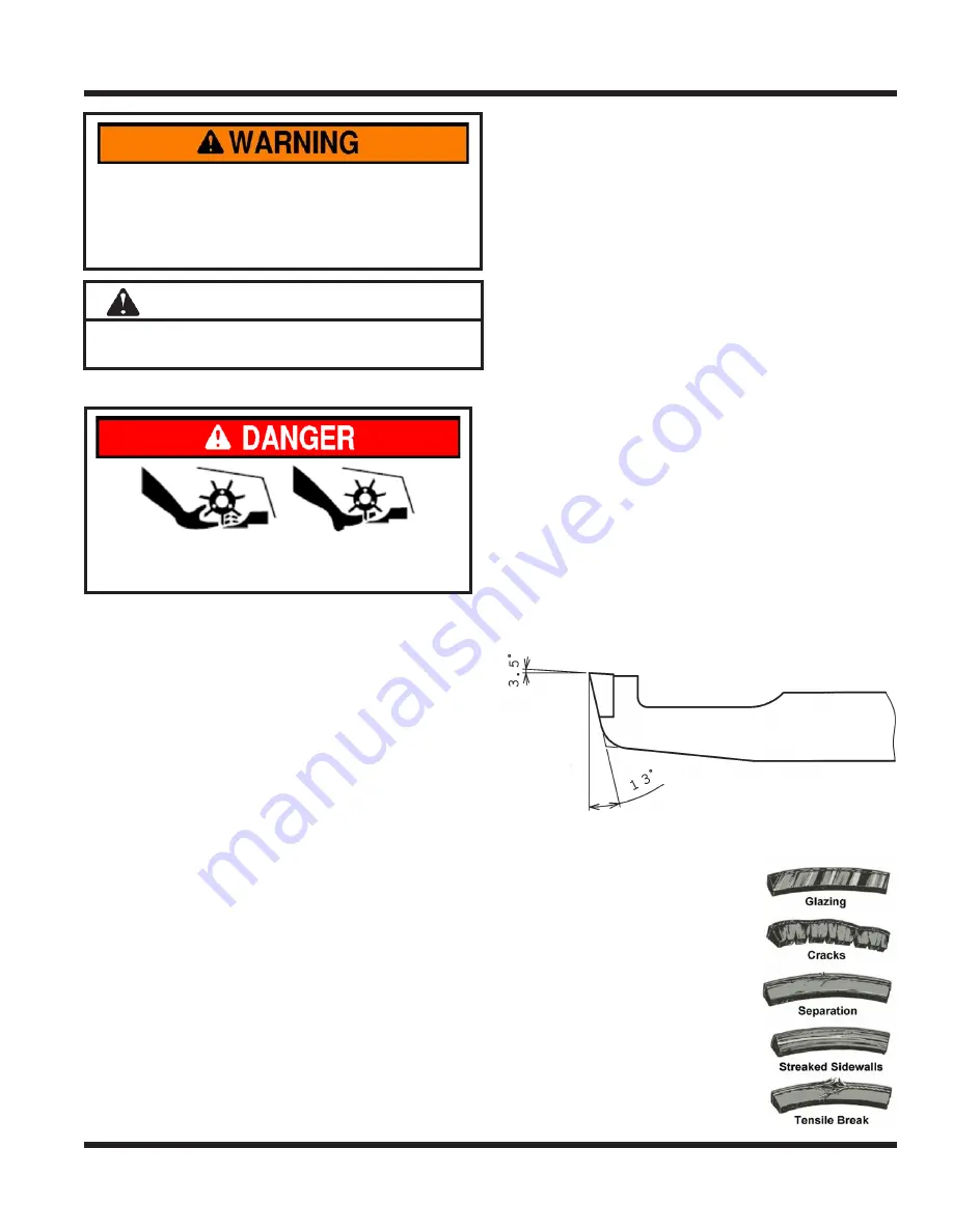
Bed Knife Grinding
Top Angle = 3.5°
Front Angle = 13°
Drive Belt Inspection/Replacement
Inspecting the drive belt on the
reel mower can prevent sudden
belt failure by finding problems
before they cause the belt to
break.
Typical wear on the drive belt
may result in the conditions
shown in the diagram. If any of
these conditions occur, the drive
belt will require replacement.
SERVICE
Always set the parking brake, shut off power
unit engine, remove the ignition key, and ensure
all moving parts have come to a complete stop
before inspecting components or attempting any
repair or adjustment.
Attention
If any component requires replacement, use only
original Ventrac replacement parts.


