background image


Re vised  05/17/18

09.10014

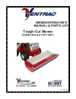
OWNER/OPERATOR’S

MAN UAL & PARTS LIST

Tough-Cut Mower

HQ680 (Serial # 1001-1901)

Summary of Contents for Ventrac HQ680

Page 1: ...Revised 05 17 18 09 10014 OWNER OPERATOR S MANUAL PARTS LIST Tough Cut Mower HQ680 Serial 1001 1901 ...

Page 2: ...l and Serial numbers Please fill in the following information for future reference See picture below to find the location of the identification number Record them in the spaces provided below Date of Purchase Month _________________ Day ___________ Year ___________________ Dealer _______________________________________________________________________ Dealer Address ________________________________...

Page 3: ...ips C 3 4 Duals C 5 Swivel Wheel Cutting Height Guide C 5 MAINTENANCE Section D Lubrication D 1 Removal Reinstallation of Blades D 2 Sharpening Blades D 2 Storage D 2 Belt Replacement D 3 Main Deck Belt Replacement D 3 Right Belt Replacement D 3 Drive Belt Replacement D 3 PARTS ILLUSTRATED DRAWINGS Section E Main Deck E 1 2 Hitch Arms E 3 4 Spindles Serial AA1007 AA1275 E 5 6 Spindles Serial AB127...

Page 4: ...g the VENTRAC s 4000 series many attachments Variables in tractor hitch heights can be accommodated by properly positioning the hitch pins in the deck frame Easy servicing is provided by the hinged and removable cover and deck tilt to access the underside and blades Power consumption is always relative to numerous factors but generally the Tough Cut operates easily and does not necessarily require...

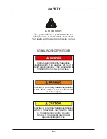
Page 5: ...ous situation which if not avoided may result in minor or moderate injury and or property damage It may also be used to alert against unsafe practices Indicates a potentially hazardous situation which if not avoided could result in death or serious injury Indicates an imminently hazardous situation which if not avoided will result in death or serious injury This signal word is limited to the most ...

Page 6: ...g Moving Part Hazard 00 0101 C E 1 27 Danger Pinching Hazard 00 0102 D E 1 15 2 Keep Hands and Feet Away 00 0123 E E 3 35 Warning Read Owner s Manual 00 0217 SAFETY The following decals must be maintained on your Ventrac Attachment If any de cals are faded or missing contact your dealer promptly for replacements ...

Page 7: ... that all bystanders are clear of the tractor and attachment before operating Be especially careful and observant if other people are present Never assume that bystanders will remain where you last saw them Always look in the direction the tractor is moving Never direct the discharge of any attachment in the direction of people animals buildings vehicles or objects of value Immediately stop at any...

Page 8: ...areas that contain stones sticks or other foreign objects that may be thrown from the mower Rotating Blades Are Dangerous Stop the machine if a person enters the mowing area Be alert at all times drive carefully because people and especially CHILDREN can move quickly into the mowing area Shut off PTO when you are not mowing Use extra care when you come to shrubs trees or objects that may block you...

Page 9: ...g E 1 for further reference Remove the outer nut from the latch handle insert the bolt through the jack stand and replace the nut Adjust spring tension as tight as possible while still allowing the jack stand latch to operate freely in and out of the notch when raising or lowering the jack stand When mowing or transporting the jack stand should always be in the very top setting Refer to pg C 2 For...

Page 10: ...in which the tractor is operated Detaching Park the tractor on a level surface and set the parking brake 1 Raise the deck all the way up 2 Stop the tractor engine 3 Release the PTO lever slowly 4 Dismount and remove the PTO belt from the tractor drive pulley 5 Lower jack stand 6 Disengage the hitch latch 7 Slowly back tractor away from the mower or carefully pull the mower from the tractor by hand...

Page 11: ...ven terrain Disengage the PTO to prevent air turbulence over dusty surfaces and or when traveling over rough terrain Operator must be sitting on the tractor seat and seat belt fastened before the PTO can be engaged Have the engine rpms between 2 000 and 3 000 before engaging the PTO switch Near full engine rpms 3 600 is recommended for most mowing If a good cut can be maintained and there is suffi...

Page 12: ...nditions If the grass is tall or mowing conditions are difficult use LOW range When mowing slopes always use LOW range with the engine at full throttle CAUTION Always shift transaxle range with the tractor parked on LEVEL ground Never shift on a slope since all hydraulic braking capacity will be lost during the shifting process Many different circumstances and situations can occur for which the op...

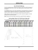
Page 13: ...s for increased stability If you are uncertain about the need for duals you should favor using them for your own SAFETY When using the mower deck both traction boosters should be engaged to increase stability and provide safer operation Note Factory recommends heavy axle kit to be used with all dual installations Cutting Height Guide for 70 8054 Swivel Wheel Kit Use the following chart to set the ...

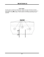
Page 14: ...are located as shown below Apply 2 3 pumps of grease per spindle approximately every 50 hours of operation All other bearings one pump max Do not over grease In very dirty sandy or wet conditions more frequent greasing may be advisable D 1 ...

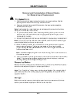
Page 15: ...he bolt head 5 When installing a blade the wood block must be placed on the opposite side to prevent rotation Tighten so that blade is firmly held in place Approximately 65 ft lbs Remember Use the correct right and left hand bolts as described in 4 Note Additional tightening will occur while mowing This is natural because of rotational torque 6 Always install the spindle guard between the bolt hea...

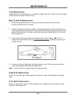
Page 16: ...belt to the right double groove pulley rotating the belt 1 4 turn into the pulley groove 3 Once around the pulley follow the diagram to the other pulleys Note The V shape of the belt should fit nicely into each pulley groove Belt twist should never exceed 1 4 turn 4 Tension the belt by tightening the idler adjustment rod The spring loops should have approximately 05 inches between them Note a rule...

Page 17: ...PARTS MANUAL HQ680 ...

Page 18: ...ILLUSTRATED DRAWING MAIN DECK E 1 PARTS DRAWINGS ...

Page 19: ...SF 1 2 13 USS 1 22 85 B0027 BUSHING 1 2 ID X 5 8 OD X 5 8 2 23 40 0292 IDLER ARM RT SIDE HQ680 1 24 95 06 WASHER FLAT 3 8 SAE 13 25 41 0066 SPRING SINGLE TORSION LH 1 26 90 0832 BOLT 1 2 13 USS X 4 1 27 00 0102 DECAL DANGER PINCHING HAZARD 1 28 00 0062 DECAL DANGER SHIELD MISSING 1 29 99 SF04 NUT SF 1 4 20 USS 2 30 90 0406 BOLT 1 4 20 USS X 3 4 2 31 05 0095 BUMPER RUBBER CYLINDRICAL 2 32 44 0209 B...

Page 20: ...ILLUSTRATED DRAWING HITCH ARMS E 3 PARTS DRAWINGS ...

Page 21: ...15 41 0048 SPRING EXT 1 OD X 6 1 16 40 0293 IDLER ARM HITCH HQ680 1 17 40 0291 IDLER ARM PIVOT HQ680 1 18 95 08 WASHER FLAT 1 2 SAE 2 19 02 CP0406 COTTER PIN 1 8 X 3 4 1 20 81 B045 BELT B45 1 21 99 SF0506 BOLT SF 5 16 18 USS X 3 4 2 22 62 0899 HITCH ARM LEFT HQ680 1 23 80 0312 SHAFT MOWER DRIVE HQ680 1 24 62 0898 HITCH ARM RIGHT HQ680 1 25 85 K0410 KEY 1 4 X 1 1 4 2 26 83 H16S BUSHING 1 SPLIT 1 4 ...

Page 22: ...ILLUSTRATED DRAWING SPINDLES Serial AA1007 AA1275 E 5 PARTS DRAWINGS ...

Page 23: ...DLE RH THREAD Serial 1001 1149 2 11 87 0206 1 SHAFT SPINDLE FLANGE RH Serial 1150 2 12 87 0184 1 SHAFT SPINDLE LH THREAD Serial 1001 1149 1 12 87 0205 1 SHAFT SPINDLE FLANGE LH Serial 1150 1 13 87 0184 ASSEMBLY SPINDLE LH Serial 1001 1149 1 13 87 0205 ASSEMBLY SPINDLE LH Serial 1150 1 14 87 0176 ASSEMBLY SPINDLE RH Serial 1001 1149 2 14 87 0206 ASSEMBLY SPINDLE RH Serial 1150 2 15 79 0048 BLADE DO...

Page 24: ...ILLUSTRATED DRAWING SPINDLES Serial AB1276 AC1635 E 5b PARTS DRAWINGS ...

Page 25: ...ING STEEL 3 12 99 SF06 NUT SF 3 8 16 USS Serial 1276 1545 24 12 99 SF06 NUT SF 3 8 16 USS Serial 1546 1635 12 13 29 GF0017 RELIEF FITTING 3 14 55 0035 BEARING BALL 25MM X 62 MM 3 15 79 0048 BLADE DOUBLE CUT NO LIFT 3 16 64 0688 GUARD SPINDLE STRING WRAPPER 3 17 91 0814 BOLT 1 2 20 SAE X 1 3 4 2 18 91 0814L BOLT 1 2 20 SAE X 1 3 4 LH ZP 1 19 87 0210 SPINDLE FLANGE SHIELD 3 20 85 W0406 KEY WOODRUFF ...

Page 26: ...ILLUSTRATED DRAWING SPINDLES Serial AD1636 E 5c PARTS DRAWINGS ...

Page 27: ...OCKING FLANGE 3 8 16 12 11 87 0226 SPINDLE ASM LH KEY 25MM CAST 1 12 79 0048 BLADE DOUBLE CUT NO LIFT 3 13 64 0688 GUARD SPINDLE STRING WRAPPER 3 14 99 B0091 WASHER 510 ID X 2 1 2 OD 1 4 3 15 91 0814 BOLT 1 2 20 SAE X 1 3 4 2 16 91 0814L BOLT 1 2 20 SAE X 1 3 4 LH ZP 1 31 87 0225 3 SHIELD SPINDLE TOP 1 32 55 0070 BEARING 30MM X 62MM X 16MM 2 33 87 0225 2 SHAFT SPINDLE RH THREAD 25MM 1 34 87 0225 1...

Page 28: ...ILLUSTRATED DRAWING COVER SHIELD E 7 PARTS DRAWINGS ...

Page 29: ...6 BOLT 5 16 18 USS X 3 4 4 6 95 05 WASHER FLAT 5 16 SAE 4 7 64 0909 BRACKET HINGE RIGHT HQ680 1 8 99 SF05 NUT SF 5 16 18 USS 4 9 02 HP0313 HAIRPIN 3 32 X 1 5 8 1 10 64 0910 BRACKET HINGE LEFT HQ680 1 11 00 0100 DECAL MADE IN USA 1 12 00 0166 DECAL BELT DIAGRAM HM HQ 1 13 95 06 WASHER FLAT 3 8 SAE 1 14 47 0127 LATCH RUBBER DRAW T HANDLE Serial 1618 2 15 99 K0072 MACHINE SCREW 10 24 X 1 2 ZP Serial ...

Page 30: ...ILLUSTRATED DRAWING 70 8054 SWIVEL WHEEL KIT F 1 PARTS DRAWINGS ...

Page 31: ...8 8 64 1160 BRACKET HQ FRONT SWIVEL 2 9 99 SF0508 BOLT SF 5 16 18 USS X 1 4 10 64 1161 BRACKET REAR MOUNT HQ 2 11 99 SF06 NUT SF 3 8 16 USS 8 12 99 SF0506 BOLT SF 5 16 18 USS X 3 4 4 13 99 SF05 NUT SF 5 16 18 USS 8 14 99 A06C LOCKNUT CENTER 3 8 16 2 15 95 06 WASHER FLAT 3 8 SAE 4 16 50 0183 YOKE CASTER 13 HIGH LOW 2 17 90 0660 BOLT 3 8 16 USS X 7 1 2 2 18 50 0050 TUBE AXLE TIRE SWIVEL FORK VM 2 19...

Page 32: ...e If this warranty covers a product used commercially or for any income producing purpose the foregoing warranties are in lieu of all other warranties and no representations guarantees or warranties express or implied including but not limited to a warranty of merchantability or fitness for a particular purpose are made by V P I in connection with the manufacture or sale of its products The engine...

Page 33: ...similar replacement equipment during the period of any warranty repair or replacement work v any telephone or telegram charges vi loss or damage to person or property other than that covered by the terms of this warranty vii any claims for lost revenue lost profit or additional cost or expense incurred as a result of a claim of breach of warranty or viii attorney s fees The remedies of buyer set f...

Reviews: