MAIN TE NANCE
D-3
Belt Re place ment:
If belts become excessively worn or cracked, install a new belt. This is done most easily
with the deck removed from the tractor.
Main Deck Belt Re place ment:
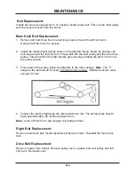
1. Remove old belt. Note that one belt loop must surround the left hitch arm.
Remove left hitch arm for access.
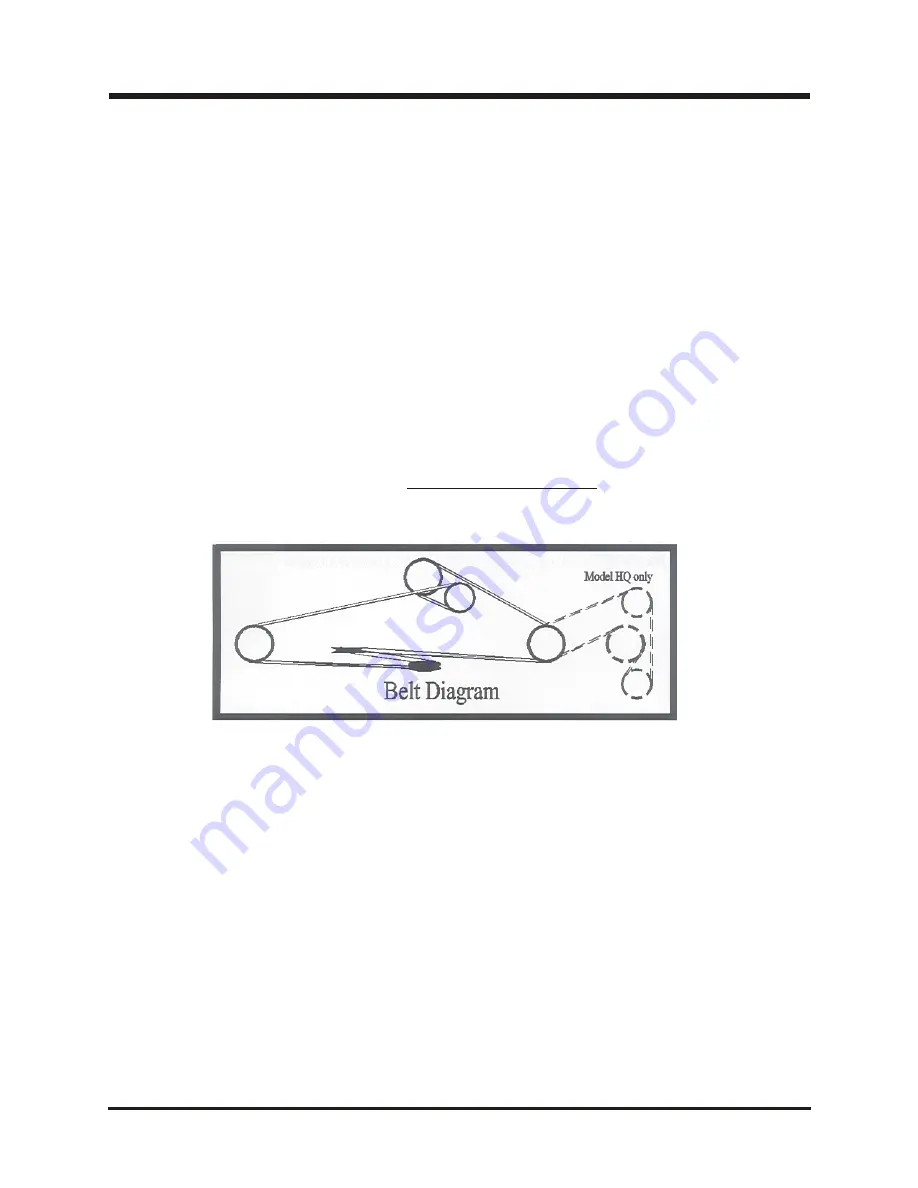
2. Install the replacement belt as shown in the diagram below. Begin by placing one
belt loop around the left hitch arm. Place belt into the idler pulley and then the drive
pulley. Take the belt to the right double groove pulley rotating the belt 1/4 turn into
the pulley groove.
3. Once around the pulley, follow the diagram to the other pulleys.
Note:
The “V”
shape of the belt should fit nicely into each pulley groove. Belt twist should never
exceed 1/4 turn.
4. Tension the belt by tightening the idler adjustment rod. The spring loops should
have approximately .05 inches between them.
Note:
a rule of thumb is to slip a paper clip between them.
Right Belt Re place ment:
Remove main deck belt. Install replacement belt as shown. Reinstall the main deck
belt.
Drive Belt Re place ment:
Remove mower from tractor. Remove pulley cover, replace belt over pulley and left
hitch arm. Reinstall cover.
Summary of Contents for Ventrac HQ680
Page 17: ...PARTS MANUAL HQ680 ...
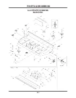
Page 18: ...ILLUSTRATED DRAWING MAIN DECK E 1 PARTS DRAWINGS ...
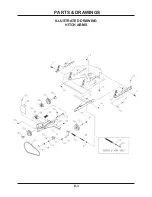
Page 20: ...ILLUSTRATED DRAWING HITCH ARMS E 3 PARTS DRAWINGS ...
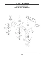
Page 22: ...ILLUSTRATED DRAWING SPINDLES Serial AA1007 AA1275 E 5 PARTS DRAWINGS ...
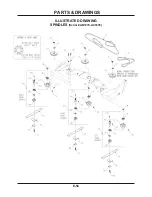
Page 24: ...ILLUSTRATED DRAWING SPINDLES Serial AB1276 AC1635 E 5b PARTS DRAWINGS ...
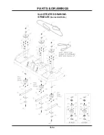
Page 26: ...ILLUSTRATED DRAWING SPINDLES Serial AD1636 E 5c PARTS DRAWINGS ...
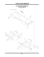
Page 28: ...ILLUSTRATED DRAWING COVER SHIELD E 7 PARTS DRAWINGS ...
Page 30: ...ILLUSTRATED DRAWING 70 8054 SWIVEL WHEEL KIT F 1 PARTS DRAWINGS ...


