OP ER A TION
C-1
Setup In struc tions for the HQ680 Tough Cut Mower
Jack Stand In stal la tion:
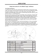
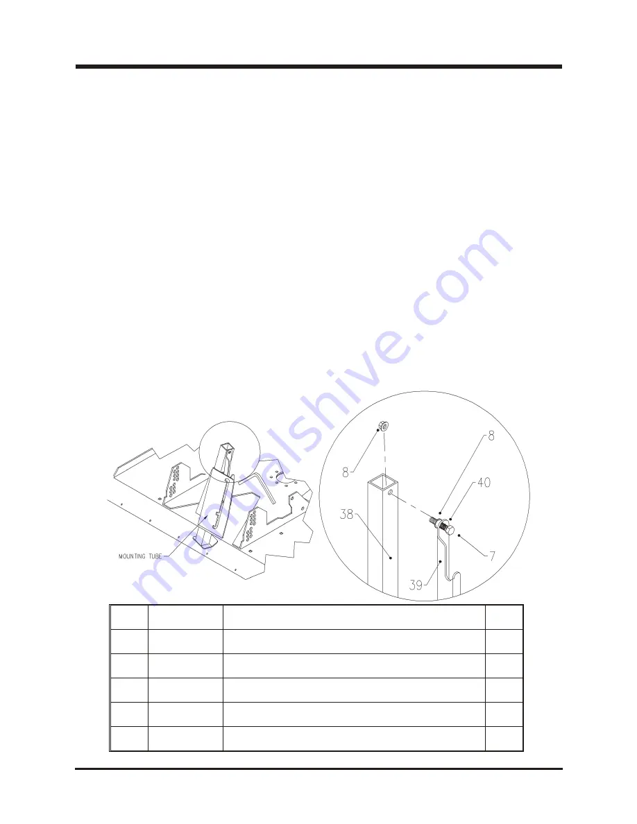
To install the jack stand into the mounting tube as shown below, raise the back of the
mower far enough to insert the stand in the tube. This can be accomplished be setting
the mower crosswise on the crate or using a lifting device. Remember, whatever
method is used keep safety in mind and use common safety procedures such as using
stands, blocking, or a restraining device.
Remove the tyton tie which holds the latch handle to the mounting tube. Insert the jack
stand into the mounting tube as shown in fig.1. Ensure that the bolt hole in the top of
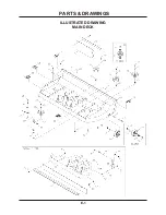
the jack stand faces to the right side of the deck. (Refer to the parts drawing on pg. E-1
for further reference). Remove the outer nut from the latch handle, insert the bolt
through the jack stand and replace the nut. Adjust spring tension as tight as possible,
while still allowing the jack stand latch to operate freely in and out of the notch when
raising or lowering the jack stand.
When mowing or transporting, the jack stand should always be in the very top setting.
(Refer to pg. C-2). For tilting the deck up, move the jack stand to the middle setting
(refer to pg. C-4). This will allow for ground clearance as well as to ensure the jack
stand does not hit the front of the tractor. To disconnect the deck from the tractor, lower
the stand to the lowest setting prior to removing the mower from the tractor. (Refer to
pg. C-2).
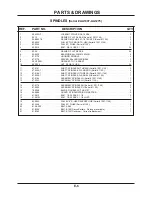
REF
PART #
DE SCRIP TION
QTY
7
90.0612
3/8-16 X 1-1/2 BOLT
1
8
99.SF06
3/8-16 FLANGE NUT
2
38
62.1011
JACK STAND
1
39
64.1114
JACK STAND LATCH
1
40
41.0039
9/16 OD X 5/8 COM PRES SION SPRING
1
Summary of Contents for Ventrac HQ680
Page 17: ...PARTS MANUAL HQ680 ...
Page 18: ...ILLUSTRATED DRAWING MAIN DECK E 1 PARTS DRAWINGS ...
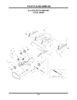
Page 20: ...ILLUSTRATED DRAWING HITCH ARMS E 3 PARTS DRAWINGS ...
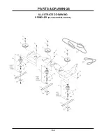
Page 22: ...ILLUSTRATED DRAWING SPINDLES Serial AA1007 AA1275 E 5 PARTS DRAWINGS ...
Page 24: ...ILLUSTRATED DRAWING SPINDLES Serial AB1276 AC1635 E 5b PARTS DRAWINGS ...
Page 26: ...ILLUSTRATED DRAWING SPINDLES Serial AD1636 E 5c PARTS DRAWINGS ...
Page 28: ...ILLUSTRATED DRAWING COVER SHIELD E 7 PARTS DRAWINGS ...
Page 30: ...ILLUSTRATED DRAWING 70 8054 SWIVEL WHEEL KIT F 1 PARTS DRAWINGS ...

