Pre-start Check List
1. Visually check for leaks, flat tires, loose wires, and loose hardware.
2. Assure parking brake is secure.
Engine Checks
1. Check fuel level.
2. Check air cleaner. Clean if necessary.
3. Check engine oil level. Add oil if necessay. See page D-3.
4. Check for engine oil leaks.
CAUTION:
Operating the engine with a blocked grass screen, dirty or plugged cooling fins,
and/or cooling shrouds removed, can cause premature engine failure due to overheating.
Hydrostatic Check
1. Check oil level. Add if necessary. See page D-3.
2. Check for hydraulic oil leaks. If a leak is discovered, repair and check oil level.
Operator Compartment Entry
1. If the tailgate is not already lowered, push forward on the chair compartment lever located
on the left side of the compartment.
2. Align the wheelchair in the middle of the tailgate/ramp and slowly enter the compartment.
3. Roll chair forward until contact is made between chair and front stops.
4. Pull back on chair compartment lever to close the tailgate. This helps secure the wheelchair
between the front stops and tailgate.
5. The tailgate (page E-3) and front stops (page E-1) are adjustable to accommodate most
wheelchairs. If proper adjustment cannot be made in securing the wheelchair, additional
stops or lockdowns of the owner’s choice must be installed.
Starting the Engine
1. Read and understand the Engine Owner’s Manual
2. Be certain all bystanders are clear of the VR300.
3. Move throttle lever approximately one-half of its travel range.
4. Move speed control lever to the neutral position. A safety switch prevents the engine from
starting in any other position.
5. Insert key into the ignition switch. Turn clockwise until the engine starts. (Do not crank
engine for more than 10 seconds at a time, and wait 60 seconds between start attempts.)
6. Before moving the VR300, allow oils to circulate and warm. Several minutes is
recommended for medium or cold conditions and approximately 20 seconds for warm
conditions.
OPERATION
C-3
Summary of Contents for VR300
Page 7: ...Safety Decal Locations SAFETY B 3 ...
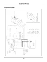
Page 19: ...Electrical Schematic MAINTENANCE D 6 ...
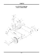
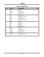
Page 20: ...PARTS E 1 ILLUSTRATED DRAWING CHAIR COMPARTMENT ...
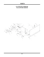
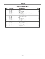
Page 22: ...PARTS E 3 ILLUSTRATED DRAWING TAILGATE MECHANISM ...
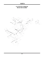
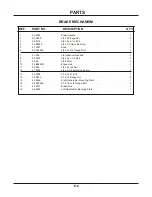
Page 24: ...PARTS E 5 ILLUSTRATED DRAWING BRAKE MECHANISM ...
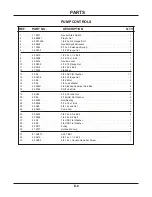
Page 26: ...PARTS E 7 ILLUSTRATED DRAWING PUMP CONTROLS ...
Page 28: ...PARTS E 9 ILLUSTRATED DRAWING DRIVE WHEEL ...
Page 30: ...PARTS E 11 ILLUSTRATED DRAWING ENGINE ...
Page 32: ...PARTS E 13 ILLUSTRATED DRAWING HANDLE BAR CONTROLS ...
Page 34: ...PARTS E 15 ILLUSTRATED DRAWING COAST LEVER ELECTRICAL PARTS ...
Page 36: ...PARTS E 17 ILLUSTRATED DRAWING SHIELDS BATTERY ...
Page 38: ...PARTS F 1 ILLUSTRATED DRAWING GUN RACK ...
Page 40: ...PARTS F 3 ILLUSTRATED DRAWING BRAKE LEVER EXTENSION ...
Page 42: ...PARTS F 5 ILLUSTRATED DRAWING RAMP TAILGATE LEVER EXTENSION ...
Page 44: ...PARTS F 7 ILLUSTRATED DRAWING TACHOMETER HOUR METER ...


