V
ENTRY
S
OLUTIONS
,
I
NC
.
16
PARTS LIST 24 INCH FRAME
Reference Part
Number Number
Quantity
01
F-1009
Leg cap, 3/4” ............................................................................................... 3
02
F-1004L
24”
Leg, rear ............................................................................................... 1
03
F-1001B
24” Frame with out wheel option ................................................................ 1
07
F-1010
Short
foam handle ....................................................................................... 2
08
F-1018
7/8
Round cap ............................................................................................. 2
09
F-1015
24”
“Seven” handle, right ........................................................................... 1
10
F296600
Rubber leg ends (jumbo crutch tips), 2” diameter ...................................... 3
13
F-1008
Roll
pins, 1¼” x 3/16” ................................................................................ 6
14
F-1007
Leg
adjustment handles ............................................................................... 3
15
F-1006
Leg
adjustment springs ............................................................................... 3
16
F-1014
24”
“Seven” handle, left ............................................................................. 1
17
F-1002L
24” Leg, left (as seen from in front of the fan) ........................................... 1
18
F-1003L
24” Leg, right (as seen from in front of the fan) ......................................... 1
19
F-1019
Motor mount bolts front with washers and nuts .......................................... 2
20
F-1022
Motor mount bolts rear with washers and nuts ........................................... 2
21
G-1024
Aluminum guard mount .............................................................................. 1
22
F-94225
Flat
socket cap screw .................................................................................. 1
24
F-7N04C
Tubing
nut
...................................................................................................
1
26
F-1024
24
Role bar .................................................................................................. 1
PARTS LIST, 24 INCH FRAME WITH WHEEL AND HANDLE OPTION
Reference Part
Number Number
Quantity
01
F-1009
Leg cap, 3/4” ............................................................................................... 6
02
F-1004L
24”
Leg, rear ............................................................................................... 1
04
F-33827
Hand
activated plunger ............................................................................... 1
05
F-1021
Lock nut washer & spring for towing handle .............................................. 1
06
F-1022
Towing handle ............................................................................................ 1
07
F-1010
Short
foam handle ....................................................................................... 4
08
F-1018
7/8
Round cap ............................................................................................. 4
09
F-1015
24”
“Seven” handle, right ........................................................................... 1
10
F296600
Rubber leg ends (jumbo crutch tips), 2” diameter ...................................... 3
11
F-1023
5/16 Wheel mounting hardware (bolts, washers, nuts) ............................... 2
12
F-1G345
Wheels 5 inch .............................................................................................. 2
13
F-1008
Roll
pins, 1¼” x 3/16” ................................................................................ 6
14
F-1007
Leg
adjustment handles ............................................................................... 3
15
F-1006
Leg
adjustment springs ............................................................................... 3
16
F-1014
24”
“Seven” handle, left ............................................................................. 1
17
F-1002L
24” Leg, left (as seen from in front of the fan) ........................................... 1
18
F-1003L
24” Leg, right (as seen from in front of the fan) ......................................... 1
19
F-1019
Motor mount bolts front with washers and nuts .......................................... 2
20
F-1020
Motor mount bolts rear with washers and nuts ........................................... 2
21
G-1024
Aluminum guard mount .............................................................................. 1
22
F-94225
Flat
socket cap screw .................................................................................. 1
24
F-7N04C
Tubing
nut
...................................................................................................
1
25
F-1004W
24 Inch frame with wheel option ................................................................ 1
27
F-1025
24
Roll
bar
with handle mount .................................................................... 1
Summary of Contents for POSITIVE PRESSURE VENTILATION FANS
Page 1: ...OWNER S MANUAL POSITIVE PRESSURE VENTILATION FANS By Ventry Solutions Inc ...
Page 5: ......
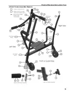
Page 20: ...POSITIVE PRESSURE VENTILATION FANS 15 20 Inch Frame Assembly Diagram ...
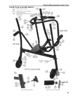
Page 22: ...POSITIVE PRESSURE VENTILATION FANS 17 24 Inch Frame Assembly Diagram ...
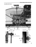
Page 26: ...POSITIVE PRESSURE VENTILATION FANS 21 Guard Mount Pictures ...
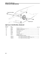
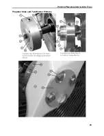
Page 28: ...POSITIVE PRESSURE VENTILATION FANS 23 Propeller Hubs and Tab Washer Pictures ...


