V
ENTRY
S
OLUTIONS
,
I
NC
.
20
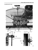
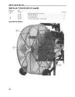
PARTS LIST FOR GUARD MOUNT
Reference Part
Number Number
Quantity
01 G-1024
Guard
mount bracket .................................................................................. 1
02 G-1035
1/8
U-bolt with nuts .................................................................................... 1
03
F94225
¼” x 1” Flat socket cap screw ..................................................................... 1
04 G-1030
Guard
mounting hardware, ¼ NF ............................................................... 2
05 G-1031
Guard
mounting
hardware, 5/16 NF ........................................................... 4
06
Guard mount spacers one of the following
G-1035
Guard mount spacers for Honda GX series motors .................................... 4
G-1036
Guard mount spacers for Honda GC135 motors ......................................... 4
07 G-1021
5/16
SAE
washers GD8 ............................................................................ 12
08
G-1020
5/16 Split lock washer GD8 ........................................................................ 4
09 G-1032
¼
Nylock GD8 ............................................................................................ 2
10 G-1037
Neobond washers ........................................................................................ 4
11
Guard, one of the following:
G-1033
20"
fan rear guard ............................................................................. 1
G-1034
24"
fan rear guard ............................................................................. 1
12
Engine, (See pages 16 and 17)1
13
Stand (see pages 12-15)
14 G-1027
¼
SAE
washers GD8 .................................................................................. 6
Note the number and position of the washers, reference numbers 7 and 14. The placement of these washers is
important to keep everything lined up properly especially for the 5/16 bolts attaching the guard to the motor crank
case. If you leave out washers the 5/16 bolts can go to deep into the blind holes and can break the engine crank
case. Please be careful
Summary of Contents for POSITIVE PRESSURE VENTILATION FANS
Page 1: ...OWNER S MANUAL POSITIVE PRESSURE VENTILATION FANS By Ventry Solutions Inc ...
Page 5: ......
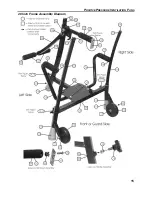
Page 20: ...POSITIVE PRESSURE VENTILATION FANS 15 20 Inch Frame Assembly Diagram ...
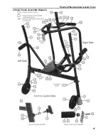
Page 22: ...POSITIVE PRESSURE VENTILATION FANS 17 24 Inch Frame Assembly Diagram ...
Page 26: ...POSITIVE PRESSURE VENTILATION FANS 21 Guard Mount Pictures ...
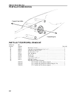
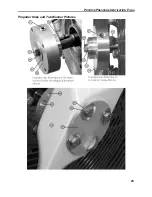
Page 28: ...POSITIVE PRESSURE VENTILATION FANS 23 Propeller Hubs and Tab Washer Pictures ...


