background image

7

www.ventilation-system.com

UNIT CONTROL PANELS

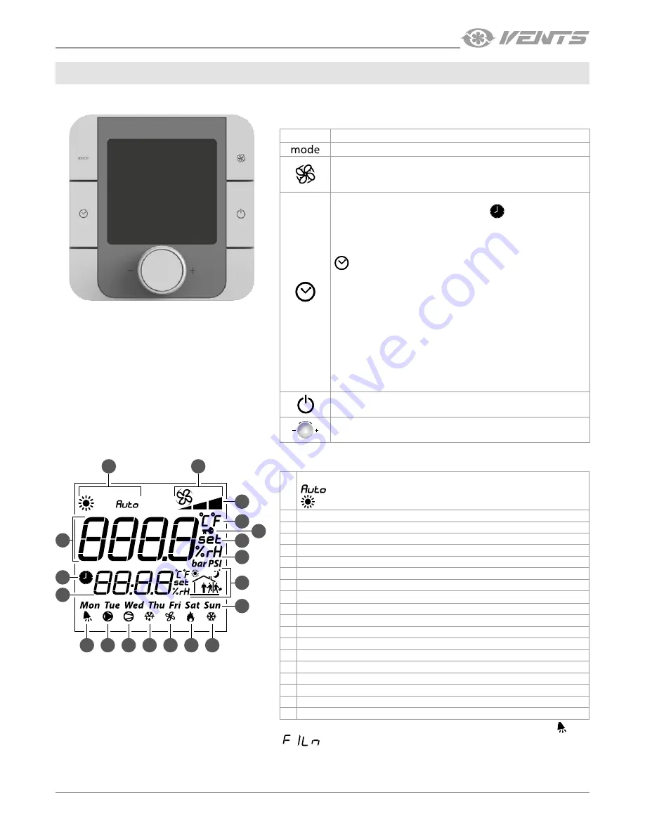
The unit is controlled via the th-Tune or pGD1 control panels.

BUTTON

FUNCTION

Auto or manual speed control selection.  

Fan speed selection: setting required speed stage (off, low, 
medium, high).

Scheduled operation on/off:  short pressing.
Activation is confirmed by a pictogram 

.

Access to the time/time range setting menu: press and hold for 
3 seconds.
Use the rotary knob to choose the necessary option:

 setting the current date/time: starts blinking. Turn the knob 

for setup.
TIMEBAND: setting the time range. Press to set the start time and 
the corresponding temperature setpoint for each time range 
individually (you may create up to four time ranges).
The pictogram shows a current day status (Day/Nigh) and time 
range status depending on the presence or absence of people 
in the house. Press ESC to exit and return to the standard display 
mode.
ESC: exit.
After 10 seconds th-Tune returns to the main menu automatically.
Unit ON/OFF. In some menus a short pressing has the same 
function as ESC.

PUSH

Setting a set point with a rotary knob.

DISPLAY SYMBOLS

1.

Reheating operation mode:

 : reheating in auto mode

 : reheating is enabled in manual mode

2.

Main field

3.

Fan mode: Manual/Auto

4.

Fan speed indicator

5.

Temperature measurement unit

6.

Lock function

7.

Setpoint value

8.

Humidity measurement unit

9.

Current time range

10. Day of the week
11. Alarm signal. An alarm reason is displayed in the controller
12. Disabled
13. Disabled
14. Disabled
15. Ventilation mode (reheating is not allowed)
16. Electric heating elements operation enable signal
17. Disabled
18. Time
19. Unit scheduled operation enabled

Upon elapsing of the set time to filter replacement the display shows the alarm symbol  and

 in the auxiliary field.

th-Tune

1

3

2

19

18

11

12

13

14

15

16

17

4

6

5

7

8

9

10

CONTROL

Summary of Contents for pGD1 (A18)

Page 1: ...pGD1 A17 th Tune A18 Automatic control system for air handling units USER S MANUAL...

Page 2: ...of ventilation systems and should be able to work in accordance with workplace safety rules as well as construction norms and standards applicable in the territory of the country The information in t...

Page 3: ...lation and maintenance operations with wet hands Do not wash the unit with water Protect the electric parts of the unit against ingress of water Do not allow children to operate the unit Disconnect th...

Page 4: ...CE OF UNIT INSTALLATION LOCATION MUST PREVENT UNAUTHORIZED ACCESS BY UNATTENDED CHILDREN PURPOSE TECHNICAL DATA Parameter Value th Tune A17 pGD1 A18 Storage temperature C from 20 to 70 from 20 to 70 S...

Page 5: ...nel 3 Complete the electrical connections as shown in the external wiring diagram 4 Secure the rear part of the control panel in the mounting box using the screws supplied 5 Reconnect the 4 pin socket...

Page 6: ...control panel on a wall route the phone cable to the selected location 1 Secure the rear part of the casing in the standard box by means of the round head screws supplied 2 Connect the phone cable to...

Page 7: ...nce of people in the house Press ESC to exit and return to the standard display mode ESC exit After10secondsth Tunereturnstothemainmenuautomatically Unit ON OFF In some menus a short pressing has the...

Page 8: ...ion temperature values pre set parameters and alarms Buttons intended for operating the controller 6P6C telephone connector The 6P6C connector PLUG 6P6C P C2 is designed for connection of the pGD1 con...

Page 9: ...perature Current date Timer mode Scheduled operation mode Current time Unit operation modes Auto Vent Heating applicable for the models with heating Fan speed Temperature setpoint fans are off speed I...

Page 10: ...the week Each day has four time ranges with set start time fan speed and temperature settings Start of each next time range means the end of the previous one Press to return to the setup menu Press t...

Page 11: ...n the timer is activated Timer mode operation has higher priority as compared to the scheduled operation If both the scheduled operation mode and the timer are activated the unit operates according to...

Page 12: ...replacement periodicity Recordingfrequency periodicity of data recording into non volatile storage Upon elapsing of the time to filter replacement the display shows the filter replacement or cleaning...

Page 13: ...ssword Otherwise access to the Engineering menu remains disabled Press to return to the setup menu Description of the Engineering menu is available for service engineers only AIR QUALITY Select Air qu...

Page 14: ...in the setup menu and press Use the and buttons to select the desired menu item and press to enter Security menu Log Out logging out and display locking Change password changing password for the user...

Page 15: ...Time time setting for automatic locking of the display from 1 up to 30 minutes Press to unlock the display Then enter the password CONFIGURATION In the setup menu select the Configuration item and pre...

Page 16: ...V159EN 01 Carel...

Reviews: