5
www.ventilation-system.com
TECHNICAL DATA
Fan design
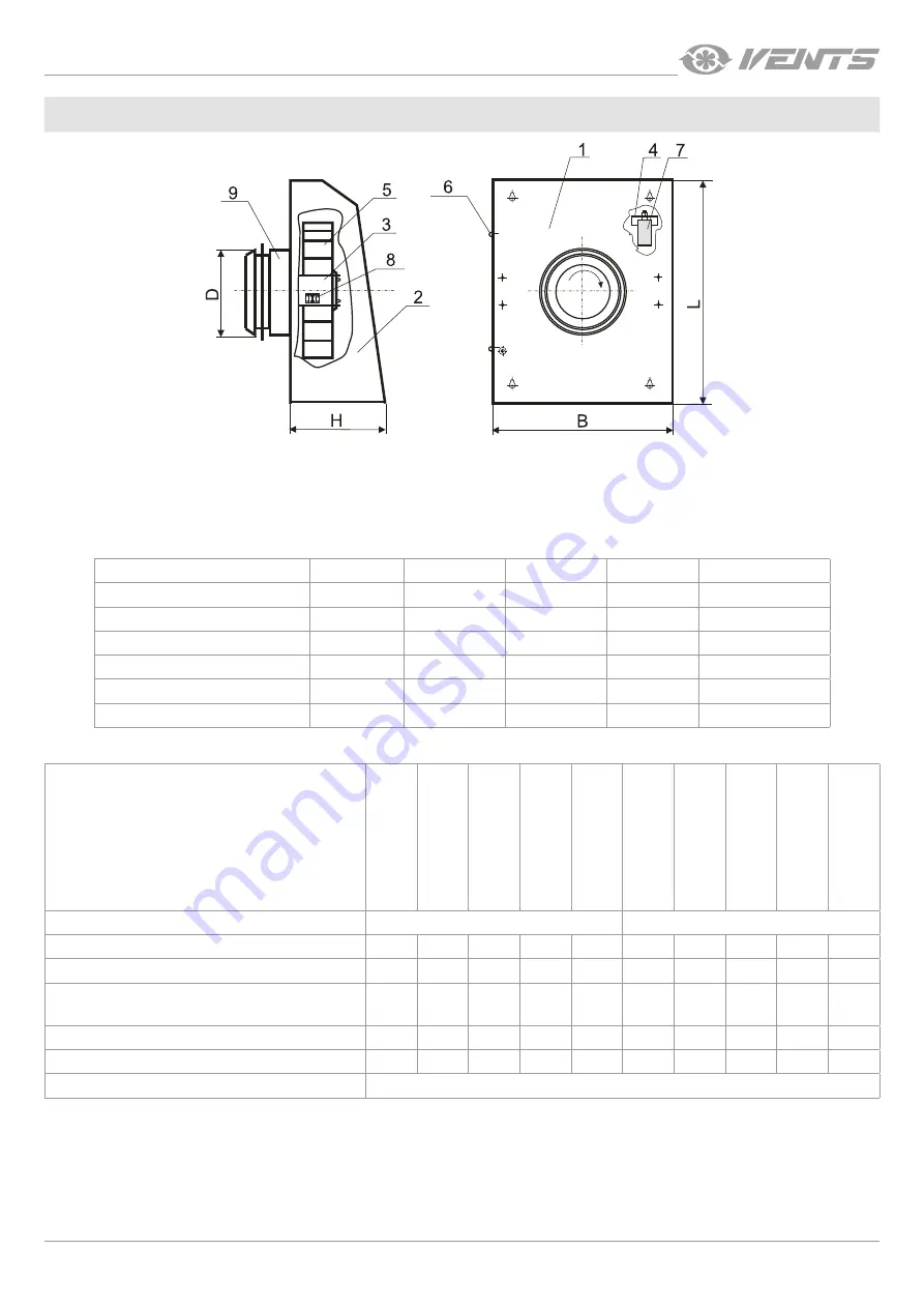
The fan consists of a casing 1 with a cover 2 that is attached by screws 6. The right-hand turbine 5 is installed inside the casing on brackets
3, 4 (not available in VCN EC modifications), a condenser 7 (not available in VCN EC modifications) and a terminal block 8 for connection
to single-phase power mains. The casing is equipped with an intake spigot 9 (VCN K modification is equipped with a backdraft damper)
for connection to an air duct.
Overall and connecting dimensions
D
L
B
H
Weight [kg]
VCN 100/VCN 100 EC
100
355
260
140
3.60
VCN 125/VCN 125 EC
125
355
260
140
3.60
VCN 150/VCN 150 EC
150
400
300
140
4.70
VCN 160/VCN 160 EC
160
400
300
140
4.70
VCN 200/VCN 200 EC
200
400
300
140
4.70
VCN 200 EC C
200
400
326
182
5.3
Technical data
VCN 100/V
CN 100 K
VCN 125/V
CN 125 K
VCN 150/V
CN 150 K
VCN 160/V
CN 160 K
VCN 200/V
CN 200 K
VCN 100/V
CN 100 K
VCN 125/V
CN 125 K
VCN 150/V
CN 150 K
VCN 160/V
CN 160 K
VCN 200/V
CN 200 K
Voltage [V]
1~230 (50 Hz)
1~230 (60 Hz)
Power [W]
71
75
96
95
96
92
98
100
96
97
Current [A]
0.31
0.33
0.42
0.41
0.42
0.40
0.43
0.44
0.42
0.42
Air flow [m
3
/h]
325
(295*)
485
(450*)
630
(565*)
650
(590*)
700
(640*)
350
(320*)
500
(465*)
650
(595*)
685
(625*)
710
(650*)
RPM [min
-1
]
2530
2475
2400
2440
2515
2625
2570
2270
2400
2555
Sound pressure level at 3 m distance [dBA]
54
54
58
60
62
54
54
58
60
62
Transported air temperature [°С]
-25...+40
*For VCN XXX K models
Summary of Contents for VCN 100
Page 12: ...V06EN 04 ...


