background image

10

VUE P3B EС

www.ventilation-system.com

MOUNTING AND SET-UP

READ THE USER'S MANUAL BEFORE INSTALLING THE UNIT.

WHILE INSTALLING THE UNIT ENSURE CONVENIENT ACCESS FOR SUBSEQUENT 

MAINTENANCE AND REPAIR. 

HUMIDITY SENSOR MOUNTING

The humidity sensor is not included in the delivery set and can be ordered separately.
The humidity sensor must be installed prior to unit mounting.
Unit mounting sequence:
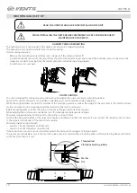
•  Remove the mounting screws of the service side panel of the unit and take it off.
•  Install the humidity sensor into the mount from the side of the extract air duct and connect the humidity sensor connector to the 

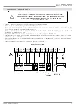
respective connector coming from the control unit, refer to the External wiring diagram.

•  Install the sensor cover back.

Washer 
Nut

Threaded rod
Vibration absorbing rubber 

min 20 mm

UNIT MOUNTING

The unit is designed for ceiling mounting with anchor threaded bolts, nuts and vibration-absorbing rubber.
Fasteners for unit mounting are not included in the delivery set and should be ordered separately.
While choosing fasteners consider the material of the mounting surface as well as the weigh of the unit, refer to the Technical Data 
section. Fasteners for unit mounting should be selected by the service technician.
Before mounting make sure that the casing  is free of any foreign objects like film or paper.
While installing the unit ensure convenient access for subsequent maintenance and repair.
Minimum required distance from the unit to the ceiling  is at least 20 mm. 
To attain the best performance of the unit and to minimise turbulence-induced air pressure losses, connect the straight air duct section 
to the spigots on both sides of the unit while mounting.
Minimum straight air duct length:
•  equal to 1 air duct diameter on intake side
•  equal to 3 air duct diameters on outlet side
If the air ducts are too short or not connected, protect the unit parts from ingress of foreign objects.
To prevent uncontrollable access to the fans the spigots may be covered with a protecting grille or other protecting device with mesh 
width not more than 12.5 mm.

Summary of Contents for VUE 100 P3B EC

Page 1: ...USER S MANUAL VUE 100 P3B EС VUE 150 P3B EС VUE 250 P3B EС VUE 350 P3B EС Heat and energy recovery air handling unit ...

Page 2: ...e of the document s preparation The Company reserves the right to modify the technical characteristics design or configuration of its products at any time in order to incorporate the latest technological developments No part of this publication may be reproduced stored in a retrieval system or transmitted in any form or by any means in any information search system or translated into any language ...

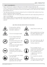
Page 3: ... operator UNIT INSTALLATION AND OPERATION SAFETY PRECAUTIONS Disconnect the unit from power mains prior to any installation operations Unpack the unit with care The unit must be grounded While installing the unit follow the safety regulations specific to the use of electric tools Do not change the power cable length at your own discretion Do not bend the power cable Avoid damaging the power cable ...

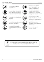
Page 4: ...stances in close proximity to the unit When the unit generates unusual sounds odour or emits smoke disconnect it from power supply and contact the Seller Do not open the unit during operation Do not direct the air flow produced by the unit towards open flame or ignition sources Do not block the air duct when the unit is switched on In case of continuous operation of the unit periodically check the...

Page 5: ...s materials coarse dust soot and oil particles or environments favourable for the formation of hazardous substances toxic substances dust pathogenic germs THE UNIT SHOULD NOT BE OPERATED BY CHILDREN OR PERSONS WITH REDUCED PHYSICAL MENTAL OR SENSORY CAPACITIES OR THOSE WITHOUT THE APPROPRIATE TRAINING THE UNIT MUST BE INSTALLED AND CONNECTED ONLY BY PROPERLY QUALIFIED PERSONNEL AFTER THE APPROPRIA...

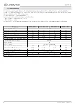
Page 6: ...s The unit design is constantly being improved thus some models may be slightly different from those described in this manual Parameter VUE 100 P3B EС VUE 150 P3B EС VUE 250 P3B EС VUE 350 P3B EС Unit voltage V 50 Hz 1 230 Maximum unit power W 66 83 84 171 Maximum unit current A 0 5 0 7 0 7 1 3 Maximum air capacity m3 h 170 215 300 430 RPM 2800 2000 2000 3200 Sound pressure level at 3 m distance d...

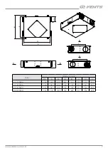
Page 7: ... B L L A B A B Model Dimensions mm Ø D A A1 B B1 H H1 L VUE 100 P3B EС 100 734 600 481 571 204 223 300 VUE 150 P3B EС 100 987 854 704 793 222 241 480 VUE 250 P3B EС 150 987 854 704 793 227 246 480 VUE 350 P3B EС 150 1157 1024 754 843 277 296 488 ...

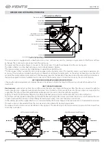
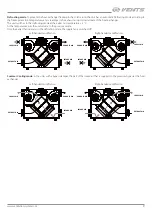
Page 8: ...idity sensor is carried out on site by the service technician LEFT HANDED AND RIGHT HANDED MODIFICATIONS Choosing the right arrangement can improve the ease of installation shorten the length of the ducts and reduce the number of air duct bends UNIT OPERATION MODES Heat recovery warm extract air from the room flows into the unit and is cleaned in the extract filter Then the air is moved through th...

Page 9: ... exhaust air duct downstream of the heat exchanger The unit switches to the defrosting mode at the extract air temperature 3 C As the temperature rises the unit returns to the previous mode Only the extract fan operates in the defrosting mode the supply fan is switched off Summer Cooling mode in the units with a bypass damper the part of the intake air that is supplied to the premises bypasses the...

Page 10: ...mounting are not included in the delivery set and should be ordered separately While choosing fasteners consider the material of the mounting surface as well as the weigh of the unit refer to the Technical Data section Fasteners for unit mounting should be selected by the service technician Before mounting make sure that the casing is free of any foreign objects like film or paper While installing...

Page 11: ...rcuit in the event of overload or short circuit The position of the automatic circuit breaker must ensure free access for quick power off of the unit The trip current of the automatic circuit breaker must exceed the maximum current consumption of the unit refer to the Technical data section or to the unit label It is recommended to select the nominal current of the circuit breaker from the standar...

Page 12: ...eat exchanger vacuum cleaning using a crevice nozzle is recommended 3 Fan maintenance once a year Even in case of regular maintenance of the filters some dust may accumulate inside the fans and reduce the fan performance and supply air flow Clean the fans with a soft brush or cloth Do not use water aggressive solvents or sharp objects as they may damage the impeller 4 Technical maintenance of air ...

Page 13: ...IONS Store the unit in the manufacturer s original packaging box in a dry closed ventilated premise with temperature range from 5 C to 40 C and relative humidity up to 70 Storage environment must not contain aggressive vapors and chemical mixtures provoking corrosion insulation and sealing deformation Use suitable hoist machinery for handling and storage operations to prevent possible damage to th...

Page 14: ...the Seller for warranty service The manufacturer s warranty does not apply to the following cases User s failure to submit the unit with the entire delivery package as stated in the user s manual including submission with missing component parts previously dismounted by the user Mismatch of the unit model and the brand name with the information stated on the unit packaging and in the user s manual...

Page 15: ...chase Date This is to certify acceptance of the complete unit delivery with the user s manual The warranty terms are acknowledged and accepted Customer s Signature INSTALLATION CERTIFICATE The VUE ______P3B EC______ unit is installed pursuant to the requirements stated in the present user s manual Installation Stamp Company name Address Phone Number Installation Technician s Full Name Installation...

Page 16: ...V146EN 04 ...

Reviews: