12
External devices.
The control panel has a built-in temperature sensor. Therefore, while installing the panel in the operating area ensure at least 1 m
clearance from heating equipment, doors and windows.
The panel is attached to the wall using the self-tapping screws supplied.
The data cable connecting the control panel and the unit shall be routed separately from the power cables. The recommended
minimum distance between the cables is 150 mm.
The control panel is supplied pre-assembled and connected to the unit by the manufacturer. If the repeat installation is necessary,
follow the following steps:
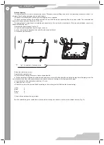
Dismantle the control panel (see Fig. 9):
a) Open the control panel box by pressing on the ends;
b) Use a screwdriver to disconnect the cable from the terminal block;
c) Disconnect the data cable.
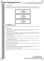
Fig. 9. Control panel disconnection
a)
b)
Attach the cable as necessary.
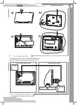
Assemble the control panel:
a) Route the cable through the access hole in the bottom lid;
b) Fix the control panel bottom lid where desired and ensure a secure fi t of the lid to the wall by tightening the self-tapping screw. The
screw head must be clear of the control panel circuit board otherwise causing a risk of equipment damage!
c) Strip the cable of the protective insulation (~20 mm);
d) Strip the wires (~6 mm);
e) Attach the wires to the terminal block according to the markings on the label and the wire colouring:
green В
brown А
white
┴
f ) Snap the control panel casing in place.
Run the cable through the sealed lead in the control unit casing and connect it to the terminal block contacts (Fig. 10).
Summary of Contents for VUT 1000 EH
Page 25: ...V28EN 04 ...


