background image

14

VUT 1500/2500/3500 PB EC

www.ventilation-system.com

Summary of Contents for VUT 1500 PB EC

Page 1: ...VUT 1500 PB EC VUT 2500 PB EC VUT 3500 PB EC Air handling unit USER S MANUAL ...

Page 2: ...tion in this user s manual is correct at the time of the document s preparation The Company reserves the right to modify the technical characteristics design or configuration of its products at any time in order to incorporate the latest technological developments No part of this publication may be reproduced stored in a retrieval system or transmitted in any form or by any means in any informatio...

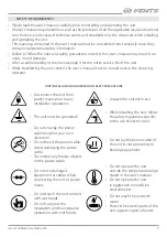
Page 3: ... operator UNIT INSTALLATION AND OPERATION SAFETY PRECAUTIONS Disconnect the unit from power mains prior to any installation operations Unpack the unit with care The unit must be grounded While installing the unit follow the safety regulations specific to the use of electric tools Do not change the power cable length at your own discretion Do not bend the power cable Avoid damaging the power cable ...

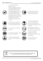
Page 4: ...and understand the risks involved Disconnect the unit from power mains prior to any technical maintenance Do not store any explosive or highly flammable substances in close proximity to the unit When the unit generates unusual sounds odour or emits smoke disconnect it from power supply and contact the Seller Do not open the unit during operation Do not direct the air flow produced by the unit towa...

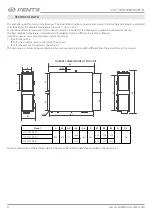
Page 5: ... 1 Packing box 1 The heat recovery air handling unit is designed for installation in centralized mechanical ventilation systems It is rated for continuous operation Transported air must not contain any flammable or explosive mixtures evaporation of chemicals sticky substances fibrous materials coarse dust soot and oil particles or environments favourable for the formation of hazardous substances t...

Page 6: ... conditions must prevent ingress of atmospheric precipitations and direct solar radiation at the ambient temperatures from 35 C up to 50 C At sub zero ambient temperatures frost protection must be provided for the drainage and pipelines connected to the unit The heat medium temperature in water heaters if available must be sufficient to prevent its freezing Hazardous parts access and water ingress...

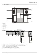
Page 7: ...panel for access to the filter located on the service side 2 panel for access to the heat exchanger and the bypass damper located on the service side 3 panel for access to the control unit and the terminal block located on the service side 4 panel for access to the filter located on the service side 5 panels for access to the fans located at the bottom of the unit 6 panels for access to the filter...

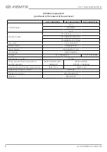
Page 8: ... HE 600x350 12 0 3 A21 DX cooler CDX 600х350 3 Water cooler CW 600х350 3 Water heater HW 600x350 2 A21 Air damper RRV P600x350 G4 filter SF 196x384x40 SF 253x603x48 Air damper actuator TF 230 Three position ball valve with an electric actuator Belimo R3020 4 B1 LR24A SR Belimo R3020 6P3 B1 LR24A SR Liquid mixing kit for the water heater USVK 3 4 4 USVK 3 4 6 Differential pressure switch DTV 500 Fl...

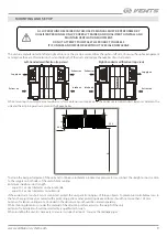
Page 9: ... between the unit and the adjoining walls are given in the figure below B B 650 350 To attain the best performance of the unit and to minimise turbulence induced air pressure losses connect the straight air duct section to the spigots on both sides of the unit while mounting Minimum straight air duct length equal to 1 air duct diameter on the intake side equal to 3 air duct diameters on outlet sid...

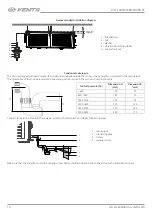
Page 10: ...mensions of the U trap are selected depending on the pressure in the section shown in the table H h Fan full pressure Pa Dimension H mm Dimension h mm 600 100 50 600 1000 140 70 1000 1400 190 95 1400 1800 240 120 1800 2200 290 145 2200 2600 340 170 Connect the spigot U trap and the sewage system with metal plastic or rubber connecting pipes min 3 1 2 3 2 4 1 drain spigot 2 connecting pipe 3 U trap...

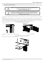
Page 11: ... unit Dust deposits on the inner parts of the unit especially in the electric heater may lead to unpleasant odours This is not a malfunction Clean the unit to eliminate odours Access to filters through side service panels Remove the service panels Unscrew the two thumbscrews securing the retaining plate Remove the filter elements Access to filters through lower service panels Remove the service pa...

Page 12: ...sive vapors and chemical mixtures provoking corrosion insulation and sealing deformation Use suitable hoist machinery for handling and storage operations to prevent possible damage to the unit Follow the handling requirements applicable for the particular type of cargo The unit can be carried in the original packaging by any mode of transport provided proper protection against precipitation and me...

Page 13: ...nual including submission with missing component parts previously dismounted by the user Mismatch of the unit model and the brand name with the information stated on the unit packaging and in the user s manual User s failure to ensure timely technical maintenance of the unit External damage to the unit casing excluding external modifications as required for installation and internal components cau...

Page 14: ...14 VUT 1500 2500 3500 PB EC www ventilation system com ...

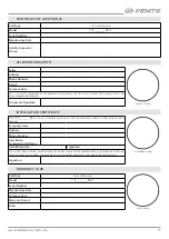
Page 15: ...N CERTIFICATE The VUT________PB EC unit is installed pursuant to the requirements stated in the present user s manual Installation Stamp Company name Address Phone Number Installation Technician s Full Name Installation Date Signature The unit has been installed in accordance with the provisions of all the applicable local and national construction electrical and technical codes and standards The ...

Page 16: ...V108 1EN 01 ...

Reviews: