9
www.ventilation-system.com
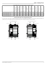
Compatibility table of optional equipment and unit models
HV1 int
er
nal
humidit
y sensor
HV2 int
er
nal
humidit
y sensor
CO2-1 r
oom sensor
CO2-2 r
oom sensor
Room humidit
y
sensor
VOC r
oom sensor (0-10 V
)
CO2 r
oom sensor (0-10 V
)
Room humidit
y
sensor
(0-10 V
)
Pr
eheat
er
Reheat
er
VUT 160/250/350 PB EC A11
+
—
—
—
—
—
—
—
+
—
VUT 160/250/350 PB EC A14
—
+
+
+
+
—
—
—
—
—
VUT 160/250/350 PB EC A21
—
+
+
+
+
+
+
+
+
+
RIGHT-HANDED AND LEFT-HANDED MODIFICATIONS
The figure below shows the arrangement of spigots for left- and right-handed modifications. Choosing the right arrangement can
improve the ease of installation, shorten the length of the ducts and reduce the number of air duct bends.
EXTRACT AIR
EXTRACT AIR
LEFTHANDED MODIFICATION
RIGHTHANDED MODIFICATION
SUPPLY AIR
SUPPLY AIR
INTAKE AIR
EXHAUST AIR
EXHAUST AIR
INTAKE AIR


