www.ventilation-system.com
14
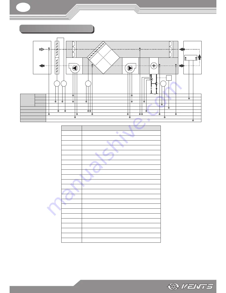
FUNCTIONAL DIAGRAM
Outside
Power supply 12 V AC
230 V AC
24 V AC
Digital input (DI)
Digital output (DO)
Analogue input (AI)
Analogue output (AO)
RS485
TE1
TE2
D1
F1
F2
RK1
D2
M2
M1
TE4
TE3
М4
TE5
Q1
Indoor
HV1
P1
HV2
TE6
SM3
SM4
SM2 SM1
DD1
400 V AC
Designation
Name
D1*
Supply air damper.
D2*
Extract air damper.
F1
Supply filter.
F2
Extract filter.
M1
Supply fan.
M2
Extract fan.
P1
Control panel.
Q1
Water heater.
HV1*
Duct humidity sensor.
HV2
Indoor humidity sensor.
RK1
Plate heat exchanger.
SM1*
Supply air damper actuator.
SM2*
Extract air damper actuator.
SM3
Bypass damper electric actuator.
SM4*
3-way valve actuator.
TE1
Intake air temperature sensor.
TE2
Temperature sensor downstream of the heat exchanger.
TE3
Return heat medium temperature sensor.
TE4
Water heater freeze protection sensor.
TE5
Air temperature duct sensor.
TE6
Room air temperature sensor.
DD1*
Pump dry run protection relay.
M4*
Circulation pump of the water heater.
* - The appliances are not supplied with the unit, are available separately.


