background image

PURPOSE 

DELIVERY 
SET 

The user's manual consisting of the technical details, operating instructions and technical 
specification applies to the installation and mounting of the heat recovery air handling unit 
VENTS VUT EH EC, hereinafter " the unit".

Due to the ability to save heating energy by means of energy recovery the unit is an important 
element of energy-efficient premises. 
The unit is a component part and is not designed for independent operation. 
The unit is designed to ensure continuous mechanical air exchange in houses, offices, hotels, 
cafes, conference halls and other utility and public spaces  as well as to recover the heat energy 
contained in the air extracted from the premises to warm up the filtered supply air. 
 
The unit is rated for continuous operation. 
Transported air must not contain any flammable or explosive mixtures, evaporation of chemicals, 
sticky substances, fibrous materials, coarse dust, soot and oil particles or environments 
favourable for the formation of hazardous substances (toxic substances, dust, pathogenic germs).

THE UNIT MAY NOT BE OPERATED BY CHILDREN OR PERSONS WITH REDUCED 
PHYSICAL, MENTAL OR SENSORY CAPACITIES, OR LACKING THE APPROPRIATE 
TRAINING. THE UNIT MUST BE INSTALLED AND CONNECTED ONLY BY PROPERLY 
QUALIFIED PERSONNEL AFTER THE APPROPRIATE BRIEFING. THE CHOICE OF UNIT 
INSTALLATION LOCATION MUST PREVENT UNAUTHORIZED ACCESS BY UNATTENDED 
CHILDREN.

The delivery set includes: 
Heat recovery air handling unit - 1 item. 
Remote mounted control panel - 1 item.
(10 m connecting cable)
User's manual  - 1 item. 
Packing box  - 1 item. 

INTRODUCTION 

WARNING 

!

3

VUT EH EC

VUT EH EC

Summary of Contents for VUT 300-1 EH EC

Page 1: ...USER S MANUAL VUT EH EC VUT EH EC ...

Page 2: ...functioning Mounting and set up Unit connection and control Condensate drainage Wiring diagram Control panel connection Unit activation deactivation Control Control panel operation Unit programming with the external control panel Error status Maintenance Troubleshooting Storage and transportation rules Manufacturer s warranty and acceptance certificate Seller information Connection certificate War...

Page 3: ...m up the filtered supply air The unit is rated for continuous operation Transported air must not contain any flammable or explosive mixtures evaporation of chemicals sticky substances fibrous materials coarse dust soot and oil particles or environments favourable for the formation of hazardous substances toxic substances dust pathogenic germs THE UNIT MAY NOT BE OPERATED BY CHILDREN OR PERSONS WIT...

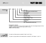
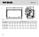
Page 4: ...ERS AND DIMENSIONS The basic unit dimensions are stated in Table 1 and in Fig 1 The basic unit parameters and characteristics are stated in the Tables 1 1 and 1 2 VUT XXX X E H EC Motor type EC electronically commutated motor Spigot direction H horizontal Heater type E electric heater Spigot diameter mm 1 150 2 160 _ 200 Air capacity m3 h 300 400 600 Unit type VUT ventilation with heat recovery 4 ...

Page 5: ...127 231 1092 1137 1198 159 500 403 161 249 555 127 231 1092 1137 1198 199 500 403 161 249 555 127 231 1092 1137 1198 199 500 403 161 249 555 127 231 1092 1137 1198 L2 L L1 B1 H3 H2 H B3 B2 B ØD B2 Model VUT 300 1 EH EC VUT 300 2 EH EC VUT 400 EH EC VUT 600 EH EC VUT EH EC VUT EH EC ...

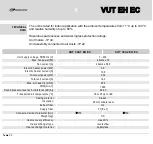
Page 6: ...nit motors IP 44 Unit assembly connected to air ducts IP 22 300 2 VUT EH EC 300 1 F7 Eu 7 VUT EH EC 2 items x 0 60 VUT EH EC VUT EH EC Unit supply voltage 50 60 Hz V Max fan power W Fan current A Electric heater power kW Electric heater current A Total unit power kW Total unit current A Max air capacity m3 h PRM min 1 Sound pressure level at 3 m distance dB A Transported air temperature C Casing m...

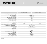
Page 7: ...er current A Total unit power kW Total unit current A Max air capacity m3 h PRM min 1 Sound pressure level at 3 m distance dB A Transported air temperature C Casing material Insulation Extract filter Supply filter Connected air duct diameter mm Weight kg Heat recovery efficiency Heat exchanger type Heat exchanger material 2 items x 175 2 items x 1 3 from 25 up to 60 Aluzinc 25 mm mineral wool max ...

Page 8: ...in an injury or unit damage After a careful reading of the manual keep it for the entire service life of the unit While transferring the unit control the User s manual must be turned over to the receiving operator Disconnect the unit from power mains prior to any installation servicing electric connection or repair operations Do not operate the unit in the air and dust mixture medium Do not operat...

Page 9: ...alance thus reducing expenses for heating in the cold seasons and air conditioning in the warm season The unit is a frame structure consisting of six 25 mm thick rigidly fixed aluzinc sandwich panels internally filled with mineral wool for sound insulation The unit components the quick detachable specially sealed service panels 14 provide maintenance access the side casing panels 13 with a termina...

Page 10: ...ponse temperature 50 C and automatic reset and another of emergency type with response temperature 90 C and manual reset supply filter 4 with filter class G4 or F7 and extract filter 5 with filter class G4 The supply filter prevent ingress of contaminants from the outdoor air to the room and prevent the unit components from contamination The extract air filters protect the unit components from con...

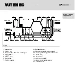
Page 11: ... Electric heater VENTS EH EC UNIT DESIGN 8 Bypass damper 9 Remote mounted control panel 10 Casing with integrated control unit 11 Drain pan 12 Data cable 13 Side unit panels 14 Quick detachable panels 15 Terminal box 1 2 3 4 5 6 7 8 9 10 11 12 13 13 14 15 Intake air Exhaust air Extract air Supply air VUT EH EC VUT EH EC ...

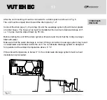
Page 12: ...ise turbulence induced air pressure losses while mounting connect the straight air duct section to the spigots on both sides of the unit Minimum straight air duct length equal to 1 air duct diameter on intake air spigot equal to 3 air duct diameter on supply air spigot Fig 5 Fig 3 Fig 4 The minimum distance for service access to the unit Location of electronic control unit If the unit supply and e...

Page 13: ...loped down by 55 mm Before starting the unit fill the drain system with water and check that the U trap is always filled with water Make sure that the water drainage is correct Wrong connection to sewage system may result in condensate accumulation inside the unit The condensate drainage system is designed for operation at the ambient temperature above 0 C If the ambient temperature is below 0 C t...

Page 14: ...14 Do not connect several drain pipes from several air handling units to a single U trap Direct condensate drainage outside without connection to sewage system is not allowed VUT EH EC VUT EH EC WARNING ...

Page 15: ...on method i e overhead in pipes or inside the walls Connect the unit to power supply on the terminal block located in the terminal box on the unit side wall in compliance with the wiring diagram and terminal designation in Fig 7 Route the cables to the terminal block in the terminal box on the unit side wall through the electric lead in to preserve the electrical protection class The external powe...

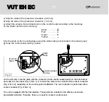
Page 16: ...need to re assemble the control panel please follow the steps below Disassemble the control panel a Press the side latches to open the control panel b Disconnect the cable from the terminal block using the screwdriver Fig 8 c Open the cable clamp on the mounting frame using cutting pliers d Remove the cable and mount the cable as required Complete mounting of the control panel Fig 8 a Route the ca...

Page 17: ...ute the cable with the connector via the electric sealed lead in in the terminal box and snap it in the socket Fig 9 item 1 or connect the wires to the contacts of the socket connector Fig 9 item 2 depending on the control panel modification The unit connection is performed with a socket connector Fig 9 item 2 The unit is equipped with thermal resistors These parts are included in the delivery set...

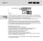
Page 18: ...own on the LCD display 4 The energy saving optimization program calculates the heater power required to sustain the indoor temperature with up to 1 C accuracy while adjusting the heater power to 1 5 The air bypass damper prevents freezing of the heat exchanger at low supply air temperature and if necessary disables intake air entering the heat exchanger in the cold ventilation mode heat exchanger ...

Page 19: ... and the control panel indicator displays the main operation window information To deactivate the unit press the Power button select Off and press the Enter button The unit switches to the heating elements cooling mode green LED is blinking and goes off in 2 minutes The operation parameters are selected and edited via the user menu see the details below UNIT ACTIVATION DEACTIVATION UNIT CONTROL Th...

Page 20: ...nd deactivation of the unit in a user defined time 3 The heat exchanger operation mode changeover enables to control the unit operation depending on the Winter or Summer season 4 Regular filter replacement must be performed to ensure cleanliness of the supply filter The automation system possesses the function of the filter replacement timer to enable timely replacement of the filter 20 1 LCD disp...

Page 21: ...back to the main working window Press Enter to enter the next menu item and edit parameters The basic operating parameters are available for editing in the main menu 5 Down button is used for going down in the list of menu or decreasing the current parameter 6 Enter button is used for selection of an editable parameter or moving to a previous menu level In the working window it indicates entrance ...

Page 22: ... Temperature setting Enables to edit the control temperature value with the Up Down buttons Fan speed Enables to edit the fan speed stage with the Up Down buttons 22 VUT EH EC VUT EH EC ...

Page 23: ...operation of the day timer and the week timer To select the item to be edited year month date day hour minute press Enter To edit the current value of the menu item use the Up Down buttons Enables to set a filter replacement interval After it elapses the control panel reminds of the filter replacement 23 VUT EH EC VUT EH EC ...
Page 24: ...orking window for some time Synchronously the red LED indicator blinks To deactivate the filter replacement indicator enter the menu item Filter replacement timer and press Enter The next filter replacement warning appears in set time period During the active indication the air handling unit operates normally Day Timer 24 VUT EH EC VUT EH EC ...

Page 25: ... in set time every day till this mode is deactivated The item Operation mode in the main window will display the symbol D to confirm that the day timer is activated Is used to program operation mode of the air handling unit for any week day If this mode is activated the unit changes its speed and control temperature automatically in set time and in set days The item Operation mode in the main wind...

Page 26: ...ation programming example The required operation schedule for the air handling unit is as follows MONDAY Set the room temperature 24 C from 08 00 till 23 00 and set the medium speed for the supply fan Set the room temperature 21 C from 23 00 till 08 00 and set the minimum speed for the supply fan TUESDAY Set the room temperature 23 C from 09 00 till 22 00 and set the maximum speed for the supply f...

Page 27: ...the day period second line Set 08 00 with the Up Down buttons and press Enter The cursor bar goes to the supply fan speed settings in the day period Set 24 with the Up Down buttons and press Enter The cursor bar goes to the room temperature settings in the day period Set medium fan speed two vertical bars with the Up Down buttons and press Enter The cursor bar goes to the activation time settings ...

Page 28: ...ursor bar goes to the room temperature settings in the night period Set 20 with the Up Down buttons and press Enter The cursor bar goes to the supply fan speed settings in the night time Set the minimum speed one vertical bar with the buttons Up Down and press Enter The cursor bar goes to the week day selection window first line Operation mode programming for WEDNESDAY In the week day selection wi...

Page 29: ... cursor bar goes to the room temperature settings in the night period Set 19 with the Up Down buttons and press Enter The cursor bar goes to the supply fan speed settings in the night time Set the minimum speed one vertical bar with the buttons Up Down and press Enter The cursor bar goes to the week day selection window first line Operation mode programming for SATURDAY In the week day selection w...

Page 30: ... temperature is below 9 C the bypass damper is open for 5 minutes and closed for 25 minutes This operation modes disables heat exchanger freezing In no heat recovery summer mode the bypass damper is always open Press the Power button to switch to the activation deactivation mode of the unit This mode is applicable only for the unit with a heat exchanger and a bypass damper 30 VUT EH EC VUT EH EC ...

Page 31: ...ating elements to prevent actuation of the overheat protection thermostats The units turns off in 2 minutes In case of actuation of any of the two overheat protection thermostats in case of filter contamination communicated by the differential pressure switch in case of communication loss the unit has an emergency shutdown The electric heater cooling mode is activated and turns off after 2 minutes...

Page 32: ...er casing Clean the heat exchanger on a regular basis to ensure high heat recovery efficiency Wash the heat exchangers with warm neutral detergent solution 3 Fan maintenance once a year Even regular technical maintenance may not completely prevent dirt accumulation in the fans which reduces the fan capacity and impairs supply air delivery into the premises Clean the fans with a soft sloth or a bru...

Page 33: ...ed with leaves and other objects reducing the unit performance and supply air delivery Check the supply grille twice a year and clean it as required 7 Air ductworks maintenance Even regular filter replacement may not completely prevent dirt accumulation in the air ducts which reduces the unit capacity The air duct maintenance includes their regular cleaning Check the outer hood and the intake gril...

Page 34: ...tact the Seller for further information regarding overcurrent in the electric circuit Low air flow Contaminated filters Contaminated air disc valves louvre shutters ventilation grilles air ducts and other system components Contaminated fans heater exchanger or other unit components Damaged air ducts Closed air dampers air disc valves or louvre shutters Clean or replace the filters Clean or replace...

Page 35: ...se screw connection No anti vibration mounts are installed Clean the fans Check the screw connection and tighten the screws if required Use the anti vibration mounts for the unit mounting available as specially ordered accessories Water leakage The drainage system is soiled damaged or frozen Wrong mounting angle of the unit or the drain system Check the mounting angle of the unit toward the drain ...

Page 36: ... years from the date of retail sale provided compliance with transport storage mounting and operation regulations In case of no confirmation of the sales date the warranty period is calculated from the manufacturing date In case of failures in the unit operation during the warranty period the manufacturer will accept reclamations and complaints from the owner of the device only after receiving tec...

Page 37: ...ial Number Manufacture Date We hereby declare that the product complies with the essential protection requirements of Electromagnetic Council Directive 2004 108 EC 89 336 EEC and Low Voltage Directive 2006 95 EC 73 23 EEC and CE marking Directive 93 68 EEC on the approximation of the laws of the Member States relating to electromagnetic compatibility This certificate is issued following test carri...

Page 38: ...g unit VUT _________ EH EC has been connected to power mains pursuant to the requirements stated in the present user s manual Company Name Address Phone Number Installation Technician s Full Name Installation Date Signature The unit has been installed in accordance with the provisions of all the applicable local and national construction electrical and technical codes and standards The unit operat...

Page 39: ...39 WARRANTY CARD Serial Number Purchase Date Warranty Period Seller Seller s Stamp Model Purchase Date VUT EH EC VUT EH EC Unit type Heat recovery air handling unit VUT ____ EH EC ...

Page 40: ...V41EN 03 VUT EH EC VUT EH EC ...

Reviews: