8
VUT 300/550/900 PBE EC
www.ventilation-system.com
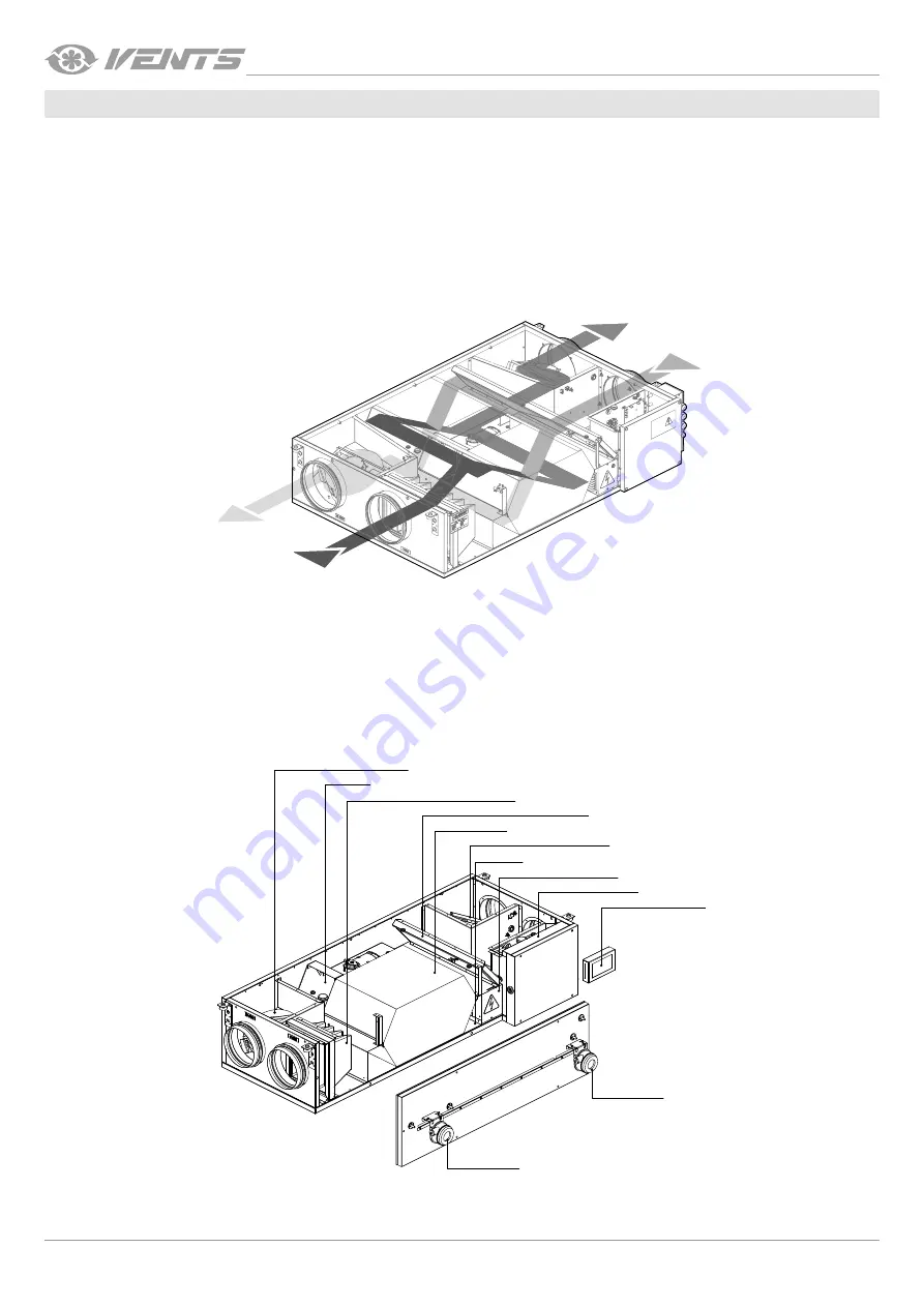
The unit operates as follows:
Warm stale extract air from the room flows through the air ducts to the unit, where it is filtered, then air flows through the heat exchanger
and is exhausted outside by the extract fan through the air ducts.
Clean cold air from outside is moved by the supply fan to the unit, where from it is directed to the supply filter. Then filtered air flows
through the heat exchanger and moves to the room through the air ducts.
Heat energy of warm extract air is transferred to clean intake fresh air from outside and warms it up.
Heat recovery minimizes thermal energy losses, energy demand and operating costs for air heating accordingly.
The unit is equipped with a detachable service panel for repair works and preventive maintenance and a cover enabling access to the
control system components.
OPERATING LOGIC
Inside
Outside
The basic unit delivery set includes a remote control panel for connection to the control system inside the unit casing.
The unit comprises a supply and an extract centrifugal single-inlet fan with forward curved blades and maintenance-free EC motors with
external rotor and built-in overheat protection, a plate counter-flow heat exchanger and an electric heater.
The supply G4 filter cleans supply air flow and prevents contamination of the unit parts.
The extract G4 filter prevents contamination of the unit components.
Some condensate may be generated during heat recovery.
The condensed fluid is collected in the drain pan and is removed from the unit through the drain hoses.
UNIT DESIGN
Extract fan
Supply filter
Extract filter
Bypass
Supply fan
Drain pan
Electric heater
Control unit
Control panel
Heat exchanger
Differential
pressure switch
Differential
pressure switch
DESIGN AND FUNCTIONING


