background image

4

VUT R EH EC

VUT R EH EC

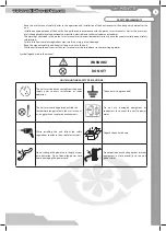
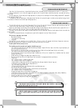
UNIT OPERATION SAFETY PRECAUTIONS

Do not touch the controller or the remote 
control with wet hands. Do not carry out the 
unit maintenance with wet hands. 

Do not wash the unit with water.
Protect the unit electric parts from water 
ingress.

Use the unit only as intended by the 
manufacturer. Do not connect a clothes dryer 
or other similar equipment to the ventilation 
system. 

Do not put any water containers on the unit. 
i.e. fl ower vases. 

Do not sit on the unit and do not put any 
objects on it.

OFF

ON

Disconnect the unit from power supply prior 
to maintenance.

Do not let children operate the unit. 

Do not damage the power cable while 
operating the unit. Do not put any objects 
on the power cable.

Keep combustible gases and infl ammable 
products away of the unit. 

Do not open the operating unit. 

In case of unusual sounds, smoke disconnect 
the unit from power supply and contact the 
service centre.

During long-term operation of the unit 
periodically check the mounting for 
reliability. 

Do not block the air duct when the unit is on. 

Do not let air fl ow from the unit be directed 
to the open fl ame devices or candles. 

Summary of Contents for VUT R 1200 EH EC

Page 1: ...USER S MANUAL VUT R 400 EH EC VUT R 700 EH EC VUT R 900 EH EC VUT R 1200 EH EC VUT R 1500 EH EC Heat recovery air handling unit ...

Page 2: ...echnical data 6 Design and operating logic 8 Mounting and set up 8 Condensate drain 11 Connection to power mains 12 Unit control 17 Maintenance 18 Troubleshooting 18 Storage and transportation rules 19 Manufacturer s warranty 19 Acceptance certificate 20 Seller s information 20 Mounting certificate 20 Warranty Card 21 ...

Page 3: ...d keep it as long as you use the unit While transferring the unit control the user s manual must be turned over to the receiving operator Symbol legend used in the manual UNIT MOUNTING SAFETY PRECAUTIONS WARNING DO NOT The unit must be disconnected from the power supply prior to every installation or repair operation The unit must be grounded The unit must not be operated outside the temperature r...

Page 4: ...t sit on the unit and do not put any objects on it OFF ON Disconnect the unit from power supply prior to maintenance Do not let children operate the unit Do not damage the power cable while operating the unit Do not put any objects on the power cable Keep combustible gases and inflammable products away of the unit Do not open the operating unit In case of unusual sounds smoke disconnect the unit f...

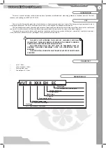
Page 5: ... clean supply air Transported air must not contain any flammable or explosive mixtures evaporation of chemicals coarse dust soot and oil particles sticky substances fibrous materials pathogens or any other harmful substances USE DELIVERY SET Unit 1 item User s manual 1 item Packing box 1 item Control panel 1 item DESIGNATION KEY VUT R ХХХ EH ЕС Unit type VUT heat recovery ventilation Heat exchange...

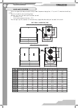
Page 6: ...75 G 333 340 340 438 460 H 200 250 250 I 670 700 700 880 1010 J 440 580 580 460 560 L 648 745 745 745 855 K 910 UNIT OVERALL DIMENSIONS MM MAINTECHNICAL PARAMETERS The unit is designed for indoor application with the ambient temperature ranging from 1 C up to 40 C and relative humidity up to 80 The unit is classified as a class I electric appliance Hazardous parts access and water ingress protecti...

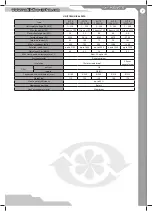
Page 7: ... 9750 Total unit current A 9 9 15 8 7 2 9 5 14 1 Max air capacity m3 h 400 700 900 1200 1500 Rotation speed min 1 up to 3100 up to 2600 up to 2600 up to 1930 up to 2000 Noise level 3 m dB A 45 52 58 60 62 Max transported air temperature C from 25 up to 60 Casing material Zinc aluminium Insulation 20 mm mineral wool 25 mm mineral wool Filter extract G4 supply G4 F7 Connected air duct diameter mm Ø ...

Page 8: ...nels are made of aluminium and galvanized sheets internally filled with heat and sound insulated material The unit is equipped with quick detachable service panels for repair and maintenance operations Route a power and a ground cable through the screwed cable glands to connect those to the terminal block located in the control unit The wiring diagram is shown on inner side of the control unit cov...

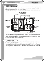
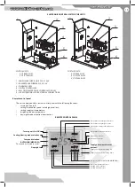
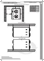
Page 9: ...n system com MINIMUM DISTANCES FOR ACCESSING TO THE UNIT UNIT CEILING MOUNTING UNIT FLOOR MOUNTING А 60 mm UNIT А VUT R 400 EH EC 800 mm VUT R 700 EH EC 900 mm VUT R 900 EH EC 900 mm VUT R 1200 EH EC 900 mm VUT R 1500 EH EC 1000 mm SERVICE SIDE ...

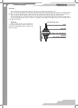
Page 10: ...ditions match the unit operation requirements before starting any installation works If the threaded bolts used for the unit mounting are too short the unit can generate abnormal noise and resonate with the ceiling If the unit connection place to the spiral seam duct is supposed to be the source of the abnormal noise install a flexible air duct instead of the flexible one Unit fixation Install an ...

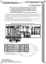
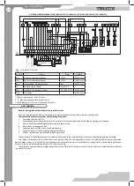
Page 11: ...ce with the wiring diagram and terminal marking Connect all the control and supply cables in compliance with the terminal marking Connect the unit to power mains through the external automatic circuit breaker with magnetic trip integrated into the fixed wiring system The rated current of the circuit breaker must match the unit current consumption refer page 7 Design Name Type Cable SM1 Supply air ...

Page 12: ...il capacity 3 Electric heater overheating protection with two thermostats 4 Rotary heat exchanger control 5 Supply and exhaust fans control and monitoring 6 Supply and exhaust air controlling damper actuating 7 System shutdown on signal from fire fighting system The controller has the following functions electric heater and rotary heat exchanger control air damper opening and closing The supply ai...

Page 13: ...ns turning unit on off setting required fan speed auto high med low setting supply air temperature displaying indoor temperature day night mode activation deactivation REMOTE CONTROL PANEL Turning unit On Off Cooling Heating mode selection Day night Fan speed selection AUTO HIGH MED LOW The speed is selected in cycles Supply air temperature set buttons Supply air temperature setting up Supply air ...

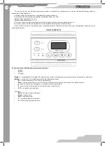
Page 14: ...1 F2 controller service buttons LED lights Power PLC power supply indicator Alarm System alarm Fault Controller alarm L1 Supply fan operation indicator L2 Extract fan operation indicator The unit has the day and the night temperature mode In each mode air temperature may be set and heated Heating mode or cooled down Cooling mode In the day mode any temperature is adjustable for heating or cooling ...

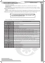
Page 15: ...gency 1 or no emergency 0 E1 Breakdown or short circuit of the intake air temperature sensor Both fans are stopped E2 Emergency system shutdown according to the signal from fire fighting system Both fans are stopped E5 Breakdown or short circuit of the supply air temperature sensor Both fans are stopped O1 Emergency system shutdown according to the signal from fire fighting system Both fans are st...

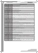
Page 16: ...cted by the engineer password factory setting 2222 Electric heater adjustment Adjust heater Electric heater adjustment menu E 01 1 Time required for heat removing from the electric heating element after the unit is off min Е 02 600 Time required to determine too low supply air temperature sec If during the fan operation the supply air temperature remains below the E 03 parameter after completion o...

Page 17: ...rature is generated if supply air temperature measured by the temperature sensor TE5 is below the set value E 03 within time period E 02 after the unit start This alarm indicates malfunction of the electric heater In case of this alarm the electric heater is turned off and both fans are shut down D1 Supply air damper RK1 Rotary heat exchanger D2 Extract air damper SM1 Supply damper actuator F1 Sup...

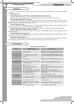
Page 18: ...ir delivery Check the supply duct grill twice a year and clean it as required 6 Duct system check every 5 years Even regular fulfilling of all the prescribed above maintenance operations may not completely prevent dirt accumulation in the air ducts which reduces the unit capacity The air duct maintenance includes periodic cleaning or replacement of the air ducts Problems Possible reasons Fault han...

Page 19: ...in the user s manual Contact your Seller for warranty service The manufacturer s warranty does not apply to the following cases User s failure to provide the unit with the entire delivery package as stated in the user s manual or with missing component parts previously dismounted by the user Mismatch of the unit model and make with the respective details stated on the unit packing and in the user ...

Page 20: ...mpliance of the product with the requirements relating to electromagnetic compatibility was based on the following standards Quality Inspector s Stamp The heat recovery air handling unit VUT R ___ EH EC has been connected to power mains pursuant to the requirements stated in the present user s manual Company name Address Telephone Installation technician s full name Installation date Signature Sho...

Page 21: ...____________ ______________________________________________________________________________________________________ ______________________________________________________________________________________________________ ______________________________________________________________________________________________________ ______________________________________________________________________________...

Page 22: ...2013 V76EN 02 ...
Reviews: