14
VUTR 250/350/650 P/P2/PE/P2E EC
www.ventilation-system.com
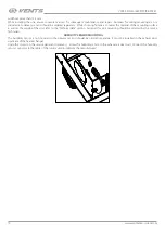
3. Fan maintenance (once per year).
Even in case of regular maintenance of the filters, some dust may accumulate inside the fans and reduce the fan performance and supply
air flow. Clean the fans with a soft cloth or brush.
Do not use water, aggressive solvents, or sharp objects as they may damage the impeller.
4. Supply air flow control (twice per year).
The supply duct grille may get clogged with leaves and other objects reducing the unit performance and supply air delivery.
Check the supply grille twice per year and clean it as required.
5. Ductwork system maintenance (once in 5 years).
Even regular fulfilling of all the maintenance operations prescribed above may not completely prevent dirt accumulation in the air ducts,
which leads to air pollution and reduces the unit capacity. Duct maintenance means regular cleaning or replacement.
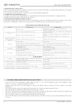
POSSIBLE REASONS AND TROUBLESHOOTING
Problem
Possible reasons
Troubleshooting
The fan(s) does not start when
the unit is on.
No power supply.
Make sure the power supply line is connected correctly, otherwise
troubleshoot a connection error.
The motor is jammed, the impeller blades are soiled.
Turn the unit off. Troubleshoot the motor jam and the impeller clogging. Clean
the blades. Restart the unit.
Alarm in the system. System alarms are listed below.
Identify the system failure by entering the active alarms menu and eliminate
the alarm.
If the system alarm cannot be eliminated by the user, contact the Seller.
Automatic circuit breaker
tripping following the unit
turning on.
High current consumption caused by a short circuit.
Turn the unit off. Contact the Seller.
Low air flow.
Low set fan speed.
Set higher speed.
The filters and the fans are clogged, the heat exchanger is clogged.
Clean or replace the filters, clean the fans and the heat exchanger.
Ventilation system elements (air ducts, diffusers, louver shutters, grilles) are
clogged, damaged or closed.
Clean or replace the ventilation system elements, such as air ducts, diffusers,
louvre shutters, grilles.
Cold supply air.
The extract filter is soiled.
Clean or replace the extract filter.
The unit operates in Cooling mode.
Check the unit operation settings.
Noise, vibration.
The impeller(s) is soiled.
Clean the impeller(s).
The fan or casing screw connection is loose.
Tighten the screw connection of the fans or the casing against stop.
No anti-vibration connectors on air duct pipe flanges.
Install anti-vibration connectors.
SYSTEM ALARMS
Fire alarm.
Emergency system shutdown on command from the fire alarm board. This
alarm interrupts the fan operation.
In case of such alarm follow the emergency instructions and leave the room
and the building.
Temperature sensor failure.
Interruption or shortening in the temperature sensor circuit. This alarm
interrupts the fan operation.
Contact the Seller.
Control panel failure.
Control panel communication error.
Check the connection of the control panel to the controller.
Contact the Seller.
Low supply air temperature.
The supply air temperature is below +14 °C (factory setting).
Clean or replace the extract filter. Check the unit operation settings.
Filter replacement required.
Filter replacement interval expiration.
Clean or replace the filters.
STORAGE AND TRANSPORTATION REGULATIONS
• Store the unit in the manufacturer’s original packaging box in a dry closed ventilated premise with temperature range
from +5 ˚С to +40 ˚С and relative humidity up to 70 %.
• Storage environment must not contain aggressive vapors and chemical mixtures provoking corrosion, insulation, and sealing
deformation.
• Use suitable hoist machinery for handling and storage operations to prevent possible damage to the unit.
• Follow the handling requirements applicable for the particular type of cargo.
• The unit can be carried in the original packaging by any mode of transport provided proper protection against precipitation and
mechanical damage. The unit must be transported only in the working position.
• Avoid sharp blows, scratches, or rough handling during loading and unloading.
• Prior to the initial power-up after transportation at low temperatures, allow the unit to warm up at operating temperature for at least
3-4 hours.


