Bx/U/2016
tel. (22) 751 95 50
www.venture.pl
fax. (22) 751 22 59
17/37
3.2 Assembly information
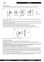
Fan need to by mounted with horizontal orientation of motor shaft (see Fig.2, the construction has to be perfectly horizontal). All assembly
holes, located on the base and foot (or vibro-isolators) have to be used. Fasteners secured against self-loosing need to be applied.
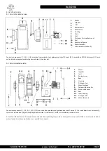
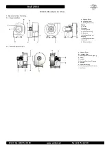
Fig. 2
Where:
A - foot
B - base
C - vibro-isolator
Supporting construction has to be solid enough in order to carry the weight of the fan and generated vibration (including fan damage). The
fan cannot be exposed to vibration.
Inlet and outlet covers preventing from touching of impeller need to be applied, according to current edition of ISO 13857 standard. Proper
covers preventing from sucking and throwing of elements (see point 1.1.2 and 1.2.3) need to be applied. The covers need to be made in
accordance with IP20 according to EN 60529.
It is recommended to apply measures minimizing transmission of vibration from/to the fan. For fans mounted in flexible form or equipped
with vibroisolators (if applied) - connecting on inlet and outlet side need to be made in flexible form.
At least 3 inlet diameters distance should be maintained between inlet, outlet and obstacles (e.g. walls, ducts bend)
Keep safe distance between installed device and inflammable elements (attention to hot surfaces of device should be paid).
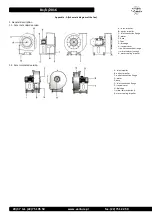
Keep safe distance between motor cooling impeller and obstacles (in accordance with motor documentation, but not less than on Fig. 3).
Measures protecting user from burn by hot elements should be applied.
3.3 Electrical connection guidelines
The fan and power supply network must be protected in accordance with local law requirements.
Detailed guidelines related to electrical connection are located in motor operation manual - those guidelines need to be applied.
Protection against short-circuits, protection against overload and voltage asymmetry need to be applied. Emergency safety switch (isolator)
near the fan should be applied.
Use appropriate protection against electric shock. Fan need to be connected to grounding system with designed for such purpose ground
terminal (terminals) – according to documentation and markings placed on motor and markings placed on fan.
Grounding protective terminal (PE) located in motor connection box need be used.
Voltage and frequency of supply network cannot exceed those indicated on the fan nameplate.
Use electrical wires with proper insulation and cross-section. Supply wires need to be placed in way excluding contact with moving elements
and in a way that liquid (e.g. from condensation) does not run over them in the connection box. Cable glands need to be properly tightened.
If the fan is equipped with thermo contact type sensor(s) (information is placed on the motor (and/or inside of connection box) and/or in
motor documentation): When permitted value of temperature is exceeded, contacts of thermocontact open, making a break in circuit. If
thermocontact sensor(s) are placed inside connection box - it need to be connected to proper system (eg. contractor, relay), which shuts
down power supply in case of exceeding permitted motor temperature.
If the fan is equipped with type PTC sensor(s) (information is placed on the motor (or inside of connection box) or in motor documentation):
PTC sensor resistance grows rapidly with exceeding of permitted motor temperature value. Ends of sensor(s) placed inside connection box
need to be connected to system, which shuts down power supply in case of exceeding permitted motor temperature.
Fig. 3


