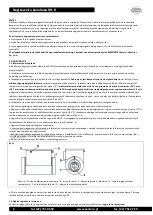
background image

Duct heater DH-R 


14 


tel. (22) 751 95 50 


www.venture.pl 


fax. (22) 751 22 59 


1.2.4 temperature 

 Housing and parts of the device during operation and for some time after switching off the device have a very high temperature. Necessary 

steps  must  be  taken  to  protect  against  scalding  and  occurrence  of  fire. 

In  the  event  of  a  fire,  to  extinguish  a  fire,  use  a  fire  extinguisher 

approved to extinguish electrical equipment and follow the instructions of the fire brigade. 


1.2.5 unexpected start / connecting power supply 

 Before  undertaking  any  kind  of  work  on  heater  (e.g. installation,  maintenance  and  inspection,  disassembly),  it  has  to  be  completely  and 

reliably disconnected (isolated) from power supply (minimum 3 mm isolating gap). It must be ensured, that power supply will not be connected 
during operation of the heater and that heating elements have cooled down to ambient temperature.   
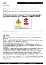
 

ATTENTION! 
BEFORE REMOVING THE COVER DISCONNECT POWER TO THE DEVICE


 The appropriate steps have to be made in order to provide protection against electric shock and to prevent access to electrical components 

by unauthorized person. 

  The heater is equipped with a control system, however, connecting the power supply results in immediate work of heating elements.   

 The  device  is  not  equipped  with  a  control  system,  which  switch  it  off  permanently  in  case  of  temporary  power  supply  loss.  It  has  to  be 

ensured, that any dangerous or unpermitted event does not occur in case of temporary loss of power supply.   

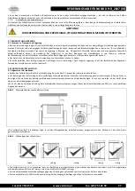
 After  disconnecting  from  power  supply,  heating  elements  and  housing,  under  influence  of  the  produced  heat  energy,  still  keep  the  high 

temperature for a certain time. It should be considered during operation. 

 Automatic temperature limiter (75°C), located in the heater, after operation (opening of the circuit) due to overheating, returns, after cooling 

down, to its original state. It has to be ensured, that any dangerous or unpermitted event does not occur in case of activation of temperature 
sensor and after its cooling down. 

1.2.6 use 

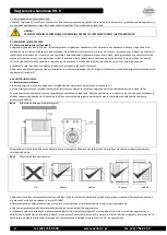
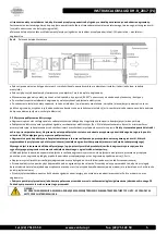
 Improper installation and/or use may lead to damage of the device and occurrence of dangerous situation. The unit can by installed, 

maintained, dismantled and used only by qualified and authorized personnel, in accordance to safety rules and current regulations in the 
country of use (including proper electrical authorization). Personnel need to be familiar with reactions caused by the heater. 

 If there is a need to open the junction box or remove the cover (eg. for maintenance or review) - involved staff must be informed about 

potential hazards and these items should be re-closed / re-assembled as soon as the maintenance / review is completed.   


Using of the device in dismantled/uncompleted state is forbidden, e.g. without the cover. 

 Any modifications of the unit are forbidden. Complicated maintenance work (such as demanding disassembly of heating elements) need to 

be always made by Venture Industries Sp. z o.o. service or with it permission - according to additional guidance. Improper assembly may lead 
to reduce the fan parameters, damage the unit and lead to the dangerous situation. 
1.2.7 Accumulation of dust 

 Please prevent the build up of dust deposits on and in the heater. Accumulation on dirt and dust can cause unpleasant odours  and risk of 

ignition. It is recommended to use appropriate air filters. 
1.2.8 explosive atmospheres 

 Contact of the heater with explosive atmospheres will cause an ignition. It is forbidden to contact the heater with explosive atmospheres. It is 

forbidden to use and store the heater in the event of the occurrence of an explosive atmosphere inside and / or around the unit. 


ATTENTION! 
ANY FLOW OF MEDIA CONTAINING A MIXTURE OF EXPLOSIVE GAS / DUST IS PROHIBITED.


2. TRANSPORT AND STORAGE 
2.1 transport and storage guidelines 

 The heater must be transported and stored in original packaging, without exposure to excessive shock. The device must be sheltered against 

adverse  weather  conditions,  stored  in  a  dry  and  ventilated  environment,  free  from  substances  harmful  to  the  device  –  it  must  not  be 
transported or stored in a room where fertilizers, chlorinated lime, acids and other aggressive chemicals are collected. The heater has to be 
protected from entering of foreign objects. 

 During transport and storage heater must be protected from mechanical damages, including crushing. 

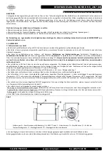
 The device must be always lifted by grasping the housing parts, using protective gloves. 

Summary of Contents for DH-R

Page 1: ...Venture Industries Sp z o o is not responsible for any damage caused by improper use of the fan and reserves the right to modify this document without informing the user DE Venture Industries Sp z o o übernimmt keine Haftung für Schäden die infolge von Nichtbeachtung der in diesem Dokument enthaltenen Hinweisen entstehen sowie behält sich das Recht vor dieses Dokument zu ändern und zu modifizieren...

Page 2: ...nicę wynosi 1 5 m s Nagrzewnica przeznaczona jest do montażu wewnątrz pomieszczenia Otoczenie nagrzewnicy nie może zawierać mieszanin wybuchowych substancji powodujących ścieranie związków agresywnych chemicznie substancji lepkich cieczy substancji o dużej wilgotności Temperatura otoczenia powinna zawierać się w przedziale 0 C do 40 C Urządzenie nie może być narażone na promieniowanie np mikrofalo...

Page 3: ...rgii elektrycznej Należy zapewnić że nie dojdzie do niebezpiecznego i niedozwolonego zdarzenia w przypadku czasowego zaniku zasilania Po odłączeniu zasilania nagrzewnicy przez określony czas grzałki i obudowa posiadają nadal wysoką temperaturę pod wpływem zgromadzonej energii cieplnej Należy uwzględnić ten fakt w trakcie użytkowania urządzenia Umieszczony w nagrzewnicy automatyczny ograniczniki te...

Page 4: ...zdział 5 3 MONTAŻ I INSTALACJA 3 1 Informacje montażowe Instalacje nagrzewnicy należy wykonać z uwzględnieniem wytycznych określonych w rozdziale 1 2 Przed przystąpieniem do instalacji należy zdjąć tymczasowe elementy chroniące nagrzewnicę przed zabrudzeniem np karton folia Pozostawienie ich podczas pracy może spowodować uszkodzenie urządzenia Należy upewnić się że urządzenie nie nosi znamion uszk...

Page 5: ...rzed skutkami zwarć oraz skutkami wystąpienia asymetrii napięcia Należy stosować odpowiednie środki ochrony przeciwporażeniowej Nagrzewnicę należy podłączyć do systemu uziemienia przy pomocy przewidzianego do tego celu punktu uziemienia PE znajdującego się w puszce podłączeniowej Nagrzewnica posiada podwójne zabezpieczenie temperaturowe realizowane poprzez połączone szeregowo ograniczniki których ...

Page 6: ... 0A 250V 3 4 WEJSCIE NC ZEZWOLENIE DZIAŁANIA PRESOSTAT 5 6 WEJŚCIE NO NOCNA OBNIŻKA TEMPERATURY 7 8 WEJŚCIE ANALOGOWEGO SYGNAŁU STERUJĄCEGO 0 10V 9 10 WEJŚCIE GŁÓWNEGO CZUJNIKA TEMPERATURY 11 12 WEJŚCIE ZADAJNIKA TEMPERATURY 13 14 WEJŚCIE CZUJNIKA TEMPERATURY MIN MAX 15 16 WEJŚCIE CZUJNIKÓW TEMP TRIAKÓW WYPROWADZENIA 15 16 ORAZ 21 27 SĄ PODŁĄCZONE FABRYCZNIE I NIE NALEŻY ICH ZMIENIAĆ 3 3 Wytyczne ...

Page 7: ... wymagane jest podłączenie zewnętrznego czujnika temperatury W trybie tym funkcja nocnej obniżki temperatury nie jest aktywna patrz schemat nr 6 5 W przypadku sterowania nagrzewnicą z użyciem czujnika pomieszczeniowego należy stosować dodatkowy czujnik temperatury w kanale tak by ograniczyć maksymalną temperaturę powietrza na wylocie z nagrzewnicy do 60 o C oraz 40 o C w miejscu nawiewu Należy w t...

Page 8: ...ia przekaźnikowego ALARMU styk zwierny 1A 250V max 6 2 Podłączenie presostatu wejście bezpotencjałowe 6 3 Podłączenie zegara sterującego nocną obniżką temp wejście bezpotencjałowe 6 4 Podłączenie zewnętrznego sygnału zadającego temperaturę wejście sygnału analogowego 0 10VDC 6 5 Podłączenie zewnętrznego sygnału sterowania mocą wejście sygnału analogowego 0 10VDC ...

Page 9: ...peratury TGK 330 nastawa wewnętrzna 6 7 Podłączenie czujnika temperatury TGK 330 nastawa zewnętrzna TBI 6 8 Podłączenie czujnika temperatury TGK 330 nastawa zewnętrzna TG R430 6 9 Podłączenie czujnika temperatury z nastawnikiem TG R430 oraz czujnika limitu temperatury TGK 360 6 10 Podłączenie czujnika temperatury TG R530 oraz czujnika limitu temperatury TGK 360 nastawa wewnętrzna ...

Page 10: ... tabliczce znamionowej W przypadku zadziałania dowolnego zabezpieczenia elektrycznego awarii należy niezwłocznie wycofać urządzenie z użytku Do oględzin urządzenia można przystąpić dopiero po jego ostygnięciu W przypadku zadziałania ogranicznika niesamoczynnego 85 C układ zabezpieczający zostaje otwarty aż do momentu zamknięcia obwodu poprzez wciśnięcie przycisku RESET umieszczonego na obudowie W ...

Page 11: ...ą uszkodzone czy aparatura zabezpieczająca jest sprawna i odpowiednio ustawiona czy ochrona przeciwporażeniowa jest skuteczna czy nie nastąpiło mechaniczne uszkodzenie nagrzewnicy elementy grzejne skrzynka przyłączeniowa itp czy nie nastąpiło zwarcie w puszce przyłączeniowej wilgoć itp na wartość oporności izolacji grzałek elektrycznych nie powinna być niższa niż 1 0MΩ czy stan elementów złącznych...

Page 12: ...Nagrzewnica kanałowa DH R 12 tel 22 751 95 50 www venture pl fax 22 751 22 59 ZAŁĄCZNIK A Deklaracja producenta ...

Page 13: ...us substances liquids substances with high humidity The ambient temperature should be between 0 C to 40 C The device must not be exposed to radiation such as microwave UV laser x ray Housing heater is made of galvanized sheet metal heating rods are made of stainless steel The heater is fitted as standard with dual protection against overheating automatic limiter temp 75 C and manual limiter with m...

Page 14: ...rous situation The unit can by installed maintained dismantled and used only by qualified and authorized personnel in accordance to safety rules and current regulations in the country of use including proper electrical authorization Personnel need to be familiar with reactions caused by the heater If there is a need to open the junction box or remove the cover eg for maintenance or review involved...

Page 15: ... The heater is to be installed in such a way as to prevent of touching the heating elements of the working device Applied protection must at least be in accordance with ISO 13857 It must be used appropriate covers to protect the device against entering of foreign element into device It is recommended to apply protective measures to minimize the transmission of vibration to the heater The device mu...

Page 16: ...ouble thermal protection provided by limiters connected in series which outputs are connected to the terminal block activation of limiters will cause the opening of the security circuit It is required to use the circuit disconnecting eg by contactor or relay the power supply of the heater and optional signalling overheating at the moment of activation of any of the temperature limiters The connect...

Page 17: ...MISSION SWITCH 5 6 INPUT NO NIGHT SETBACK 7 8 INPUT ANALOG CONTROL SIGNAL 0 10V 9 10 MAIN INPUT TEMPERATURE SENSOR 11 12 INPUT TEMPERATURE CONTROLER 13 14 INPUT TEMPERATURE SENSOR MIN MAX 15 16 INPUT OF TEMPERATURE SENSORS TRIACS OUTPUTS 15 16 AND 21 27 SĄ ARE FACTORY CONNECTED AND SHOULD NOT BE CHANGED 3 3 CONTROL GUIDELINES The heaters DH R are equipped with the internal control system AHR 15T F...

Page 18: ...ter control with a room sensor it has to be used an additional temperature sensor in the channel so as to limit the maximum air temperature at the outlet of the heater to 60 C and 40 C at the point the heater is blowing For those purposes it should be used a potentiometer Max C and to limit the minimum temperature in the channel can also be used the temperature sensor potentiometer Low C Channel s...

Page 19: ...Connection of a relay output ALARM NO contact 1A 250V max 6 2 Connection of a high pressure switch potential free input 6 3 Connection of clock controller for night setback potential free input 6 4 Connection of an external temperature setpoint input analog control signal 0 10VDC 6 5 Connection of an external power setpoint input analog control signal 0 10VDC ...

Page 20: ...r TGK 330 internal setpoint 6 7 connection of the temperature sensor TGK 330 external setpoint TBI 6 8 connection of the temperature sensor TGK 330 external setpoint TG R430 6 9 connection of the temperature sensor with the setpoint TG R430 and the temperature limit sensor TGK 360 6 10 connection of the temperature sensor TG R530 and the temperature limit sensor TGK 360 external setpoint ...

Page 21: ...e of activation of any electrical protection detection of damage unit must by immediately turn out off use The inspection device can start only after it has cooled down In the case the manual limiter is activated 85 C protection circuit is opened until the closure of the circuit by pressing the RESET buton on the housing In the event the alarm operation controller AHR 15T is activated the alarm ou...

Page 22: ...er the safety equipment is set and functioning properly and whether the shock protection is effective occurrence of mechanical damages of the heater heating elements junction box etc whether there is no short circuit in the junction box humidity etc the value of the insulation resistance of electric heating elements not lower than 1 0MΩ The appropriate condition of fasteners fasteners are tightene...

Page 23: ...OPERATION MANUAL NO DH R_2017 EN tel 22 751 95 50 www venture pl fax 22 751 22 59 23 APPENDIX A Declaration of Manufacturer ...

Page 24: ...Duct heater DH R 24 tel 22 751 95 50 www venture pl fax 22 751 22 59 Place for user notes ...

Page 25: ...den Raum 40 C nicht überschreiten Die minimale Geschwindigkeit der den Lufterhitzer durchströmenden Luft beträgt 1 5 m s Der Lufterhitzer ist für den Einbau im Inneren eines Raumes vorgesehen Die Umgebung des Lufterhitzers darf keine Explosivmischungen abriebfördernde Substanzen chemisch aggressive Stoffe klebrige Substanzen Flüssigkeiten oder Substanzen mit hohem Feuchtigkeitsanteil enthalten Die...

Page 26: ...n Betrieb der Heizelemente Das Gerät besitzt kein System zur dauerhaften Abschaltung beim Stromausfall Es ist dafür zu sorgen dass ein kurzzeitiger Stromausfall keine gefährlichen oder unerlaubten Ereignisse zur Folge haben kann Nach der Abschaltung des Lufterhitzers bleibt die Temperatur der Heizelemente und des Gehäuses auf Grund der eingespeicherten Wärme durch eine bestimmte Zeit sehr hoch Die...

Page 27: ... Gehäuseteilen unter Verwendung von Schutzhandschuhen zu heben Es wird empfohlen dass die Lagerungszeit nicht länger als ein Jahr beträgt Nach längerer Lagerung ist vor der Installation der allgemeine Zustand des Lufterhitzers zu prüfen Kapitel 5 3 MONTAGE UND INSTALLATION 3 1 Allgemeine Informationen Aufbau des Lufterhitzers ist unter Berücksichtigung der im Kapitel 1 2 genannten Hinweise durchzu...

Page 28: ...Schaltplan Abb 5 durchzuführen Es sind ein Schutztrenner mit einem Isolationsabstand von mindestens 3mm ein Kurzschlussschutz sowie ein Schutz gegen die Folgen von Phasenasymmetrie einzusetzen Es sind entsprechende Stromschlagschutzmaßnahmen zu verwenden Der Lufterhitzer ist an eine Erdungsanlage mittels des dazu vorgesehenen in der Anschlussdose befindlichen Erdungspunktes PE anzuschließen Der Lu...

Page 29: ...eratur Max o C Einstellung der Höchsttemperatur Achtung Die Einstellungen Min und Max werden nur nach dem Anschluss des Grenztemperaturfühlers an die Klemmen 13 14 berücksichtigt der Fühler wird automatisch entdeckt FUNKTIONEN DER KONTAKTBRÜCKEN Int Temp der innere T oC Steller aktiv 0 10 V Analogeingang 0 10V DC aktiv Ext Reg Steuerung durch einen äußeren Regler 0 10V BESCHREIBUNG DER ANSCHLÜSSE ...

Page 30: ...In diesem Modus ist die Funktion der nächtlichen Temperatursenkung aktiv s Schaltplan Nr 6 4 Bei aufgesteckter Kontaktbrücke Ext Reg wird der Lufterhitzer durch eine externe Steuerschaltung im Bereich 0 100 Ausfüllung des Steuerzyklus ausgesteuert wobei der Erhitzer beim Signalwert 1V ausgeschaltet wird und bei 10V wird er über die Zeit tON gleich 100 des Arbeitszyklus eingeschaltet bleiben Für de...

Page 31: ... des Relaisausgangs ALARM Schließkontakt 1A 250V max 6 2 Anschluss des Differenzdruckschalter potentialfreier Eingang 6 3 Anschluss der Zeitschaltuhr zur Steuerung der nächtlichen Temperatursenkung potentialfreier Eingang 6 4 Anschluss des externen Signals der Temperatureingabe Analogeingang 0 10VDC 6 5 Anschluss des externen Signals der Leistungssteuerung Analogausgang 0 10VDC ...

Page 32: ...eraturfühlers TGK 330 innere Einstellung 6 7 Anschluss des Temperaturfühlers TGK 330 externe Einstellung TBI 6 8 Anschluss des Temperaturfühlers TGK 330 externe Einstellung TG R430 6 9 Anschluss des Temperaturfühlers mit dem Stellglied TG R430 sowie des Grenztemperaturfühlers TGK 360 6 10 Anschluss des Temperaturfühlers TG R530 sowie des Grenztemperaturfühlers TGK 360 innere Einstellung ...

Page 33: ...bereinstimmen Beim Ansprechen von beliebiger elektrischen Schutzeinrichtung oder einer Havarie ist das Gerät sofort aus dem Betrieb zu ziehen Eine Beschauung des Gerätes darf erst nach seiner Abkühlung vorgenommen werden Beim Ansprechen des nicht selbsttätigen Temperaturbegrenzers 85 C bleibt die Schutzschaltung solange offen bis der Stromkreis durch Betätigung der am Gehäuse angeordneten RESET Ta...

Page 34: ... elektrischen Leitungen unbeschädigt sind ob die Schutzvorrichtungen funktionsfähig und richtig eingestellt sind ob der Stromschlagschutz wirksam ist ob es keine mechanische Beschädigung des Lufterhitzers vorkommt Heizelemente Anschlusskasten usw ob es kein Kurzschluss in der Anschlussdose gibt Feuchtigkeit usw Widerstandswert der Heizelementeisolation darf nicht unterhalb von 1 0 MΩ liegen entspr...

Page 35: ...stehend beschriebene Produkt Benennung Typ Kanallufterhitzer DH R RH R Modell u Seriennummer alle hergestellten Einheiten Datum der CE Kennzeichnung 2015 stimmt mit den Anforderungen überein die in folgenden Richtlinien festgelegt wurden EMV Richtlinie 2014 30 EG Niederspannungsrichtlinie 2014 35 EG Folgende harmonisierte Normen wurden verwendet PN EN 60335 1 PN EN 61000 6 1 PN EN 61000 6 3 Darübe...

Page 36: ...Kanallufterhitzer DH R 36 tel 22 751 95 50 www venture pl fax 22 751 22 59 Bemerkungen des Benutzers ...

Reviews: