OPERATION MANUAL NO DH-R_2017
(EN)
tel. (22) 751 95 50
www.venture.pl
fax. (22) 751 22 59
17
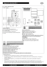
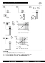
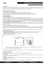
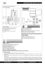
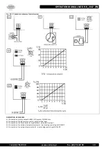
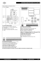
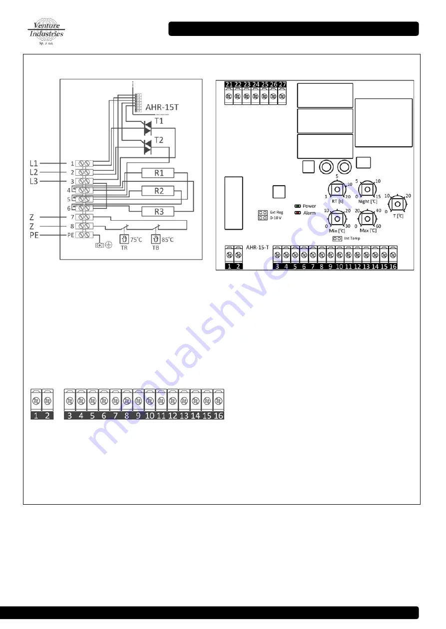
Fig. 5 Scheme of power supply connections
5.1 DH-R - power supply:
DECRIPTION OF PINS:
L1, L2, L3
– three-phase power supply of the heaters
Z
– terminals of the set of temperature limiters
PE
– protective conductor
TR
– automatic limiter
TB
– limiter with manual reset (manual limiter)
T1
– triacs
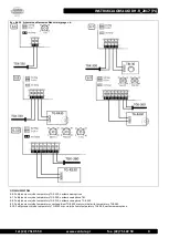
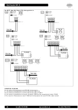
5.2 AHR-15T – control system:
DESCRIPTION OF POTENTIOMETERS:
RT [s]
- cycle length adjustment control
Night [
o
C]
– night setback setpoint
T [
o
C]
– internal setpoint of the reference value of the temperature
Min [
o
C]
– setpoint of the minimum temperature
Max [
o
C]
- setpoint of the maximum temperature
Attention! Setting min and max are taken into account only when the
temperature limit sensor is connected. To terminals 13-14, the sensor is
automatically detected.
FUNCTIONS OF JUMPERS:
Int Temp
– active internal setpoint adjuster T [oC]
0-10 V
– active input of analog signal 0-10V DC
Ext Reg
– control by an external controller (0-10V)
DESCRIPTION OF PINS:
1-2
ALARM OUTPUT POTENTIAL-FREE NO, max. 1,0A, 250V.
3-4
OUTPUT NC, OPERATION PERMISSION (SWITCH)
5-6
INPUT NO, NIGHT SETBACK
7-8
INPUT ANALOG CONTROL SIGNAL 0-10V
9-10
MAIN INPUT TEMPERATURE SENSOR
11-12
INPUT TEMPERATURE CONTROLER
13-14
INPUT TEMPERATURE SENSOR MIN-MAX
15-16
INPUT OF TEMPERATURE SENSORS TRIACS
OUTPUTS 15-16 AND 21..27 SĄ ARE FACTORY CONNECTED AND SHOULD NOT BE CHANGED
3.3 CONTROL GUIDELINES
The heaters DH-R are equipped with the internal control system AHR-15T.
For proper operation the system requires adequate connection of external accessories (eg. temperature sensor), which are not included
with the device.
Automatic control system cooperates with sensors type NTC (15÷10kΩ/0÷30
o
C) and potentiometric temperature adjusters
(0÷5kΩ/0÷30
o
C).
The microprocessor controls the switching of 2 triacs in a time cycle, by changing the activation time of heating elements of the heater in
the way to keep the setpoint temperature settings. The length of the cycle is set by a potentiometer RT [s] in the range 1÷20 s (according
to a logarithmic scale). Depending on strength of error signal (the difference between setpoint temperature and the measured value) the
activation time changes in the range from 0÷100% of the time cycle, according to the control algorithm of the controler type PI. It is not
recommended to set up too long time cycle of RT.

