Duct heater DH-R
18
tel. (22) 751 95 50
www.venture.pl
fax. (22) 751 22 59
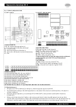
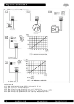
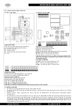
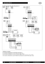
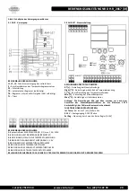
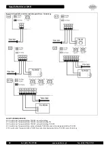
To select the setpoint temperature in the range, for example, 0 ÷ 30 ° C, it can be used the internal potentiometer T [° C] located on the
PCB controller AHR-15T (see diagram No. 6.6) or external potentiometric adjuster 0-5kΩ (eg. TBI-30, TG R430) connected to terminals
11-12 on the PCB (see diagrams No. 6.7 and 6.8). Selecting the internal or external temperature controller is via a jumper Int Temp on
the PCB (see diagrams No. 6.6, 6.7 and 6.8).
The device is equipped with a feature night setback (NO contacts, marked 5-6 on the PCB control). As a result of a short circuit contact,
temperature value will be reduced by the value set on the potentiometer Night [° C] (see diagram No. 6.3). Setting nightly reductions may
vary in the range of 0 ÷ 15 ° C.
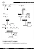
The device can be controlled by external voltage signal 0 ÷ 10V DC attached to terminals 7-8 on the PCB of the controller. Selecting the
control voltage signal is performed by setting jumpers 0-10 V. There are two control modes selectable by a jumper Ext Reg:
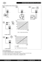
With the Ext Reg jumper removed, heater is set at the desired temperature using an external analog signal in the range of 0 ÷ 30 ° C.
The signal below <1V- will cause the turn off of the heater, and the 10V the maximum setting, ie. + 30 ° C. To work in this mode, it is
required to connect an external temperature sensor, placing of the Int Temp. jumper and setting of the potentiometer T [° C] in the
extreme left position (0 ° C). In this mode, the function of night setback is active (see diagram No. 6.4).
With the Ext Reg jumper, the heater is set by an external control system in the range 0÷100% of the operation cycle. The signal below
<1V- will cause the turn off of the heater, and the 10V activation by the time t
ON
= 100% of the operation cycle. To work in this mode, it
is not required to connect an external temperature sensor. In this mode, the function of night setback is not active (see diagram No.
6.5).
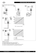
In the case of heater control with a room sensor, it has to be used an additional temperature sensor in the channel, so as to limit the
maximum air temperature at the outlet of the heater to + 60 ° C and + 40 ° C at the point the heater is blowing. For those purposes it
should be used a potentiometer Max [° C] and to limit the minimum temperature in the channel can also be used the temperature sensor
(potentiometer Low [° C]). Channel sensor 15 to 10k / 0 ÷ 60 ° C must be connected to terminals 13-14 on the PCB of the controller. The
controller detects the sensor automatically (see diagram No. 6.9 and 6.10).
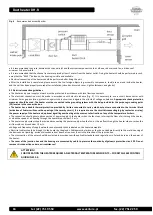
The heater is equipped with the potential free operation enable input (pins 3-4 on the PCB), the recommended way of use of it is to
connect them to the pressure switch, which controls the air flow through the heater (see scheme No. 6.2.). If this input is free, it must be
bridged. Opening input will shut down the system and issue an alarm signal (ALARM LED blinks once and the relay output 250V/1A, pins 1-
2 on PCB is shorted). operation, ALARM LED blinks twice signalling an alarm and relay output is shorted 250V/1A, pins 1-2 on the PCB
control. Alarm reset is performer automatically after the operation enable input (pressure switch) is shorted.
In case of improper connection or damage of sensors the system stops operation, ALARM LED blinks twice signalling an alarm and relay
output is shorted 250V/1A, pins 1-2 on the PCB control.
The
reset of the incorrect connection or sensor damage alarm requires
disconnecting the power supply, remediation of cause and re-application of voltage.
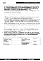
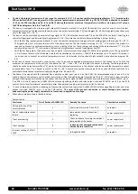
Other alarms are described in the table below:
Table of alerts:
Alert cause
No. of flashes of ALARM LED
Remedy the cause
Deactivation method
Opening the line of the
pressure switch
1
Short circuit terminals 3-4 on PCB
automatic
None / temperature sensor
failure
2
temperature sensor connection /
replacing
power supply reset
reset
Triacs overheating
3
Triacs cool down, lowering the ambient
temperature of the heater
power supply reset
reset
Triacs damage
4
replacement of damaged components -
Service Venture Industries
power supply reset
reset
Incorrect setting of MIN /
MAX
MIN/MAX
5
setting MIN<MAX
automatic

