background image

RBH/2019/V1 


tel. (22) 751 95 50 


www.venture.pl 


fax. (22) 751 22 59 


APPENDIX A - (

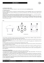
SCHEMATIC DIAGRAM OF THE FAN / LIST OF DEVICES

 
Basic elements 


1. 

fan casing


2. 

motor


3. 

base elements


4. 

cable gland


5. 

impeller cover 

6. 

Impeller 

  7.       

inlet


  8.       

base 

             
            direction of air flow 


Base elements (3) made of painted steel. Impeller (6) welded with aluminium sheet.  
 
Detailed information on applied componenets and tighten torques (not applicable to motor) have been attached to following manual an are 
available on request. 


Summary of Contents for RBH

Page 1: ...V1 valid since 30 10 2019 Venture Industries Sp z o o is not responsible for any damage caused by improper use of the fan and reserves the right to modify this document without informing the user OPE...

Page 2: ...veable components The fan is equipped with moveable components impeller Contact with them may cause serious injury or death The fan must not be used if covers grids and safety measures against contact...

Page 3: ...lectrical authorization Personnel need to be familiar with reactions caused by the fan Using of fan in dismantled uncompleted state is forbidden e g without junction box cover During the works e g mai...

Page 4: ...ds the device should be installed in such a way that prevent from getting access to the device rotor from the outlet It is recommended to use accessories to minimize the vibration transmitted from to...

Page 5: ...se slightly damp delicate material It is prohibited to use detergents liquids under pressure and tools that may scratch the unit surface After fan cleaning after end of maintenance turn on the fan for...

Page 6: ...motor 3 base elements 4 cable gland 5 impeller cover 6 Impeller 7 inlet 8 base direction of air flow Base elements 3 made of painted steel Impeller 6 welded with aluminium sheet Detailed information o...

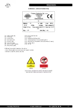
Page 7: ...tage 8 power supply frequency 9 nominal fan speed 10 motor insulation class 11 weight 12 max ambient temperature 13 max temperature of transproted medium 14 informetion of accordance with ErP Directiv...

Page 8: ...are compatible with fan nameplate Proper electrical protection is applied Grounding of fan is applied Mains supply is compatible with fan power supply Power supply disconnecting switch with 3mm visib...

Page 9: ...ge of switch or security system Failure of one of supply phases Exceeding of maximum motor speed Too low flow Failed fan start up Rubbing between fan impeller and housing or foreign body e g tool left...

Page 10: ...RBH 2019 V1 10 tel 22 751 95 50 www venture pl fax 22 751 22 59 APPENDIX E DECLARATION OF MANUFACTURER...

Page 11: ...RBH 2019 V1 tel 22 751 95 50 www venture pl fax 22 751 22 59 11...

Reviews: