


EN
Read entire booklet carefully before be-
ginning installation and save these instruc-
tions. Please contact our technical depart-
ment with any queries.
Always take into account all the specifica-
tions of the appliance that figure on the grey
label stuck to the lamp and on the installation
diagram.
To avoid damage to finish, assemble motor on
soft padded surface or use the original foam
inset in motor box. Do not lay fan on its side
as this could result in shifting of motor in dec-
orative enclosure.
To reduce the risk of personal injury, attach
the fan directly to the support structure of the
building according to these instructions, and
use only the hardware supplied.
To avoid possible electrical shock, before
installing your fan, disconnect the power by
turning off the circuit breakers to the outlet
box and associated wall switch location.
For the electrical connection it is necessary
to incorporate an isolator switch according
to the installation regulations, which ensures
all-pole cut, directly connected to the power
terminals and it must have a contact sepa-
ration in all its poles, which provides total
disconnection under category III surge con-
ditions.
All wiring and connections must be made in
accordance with national and local electrical
codes.The ceiling fan must be earthed in or-
der to prevent possible electric shock. If you
are not familiar with the way to do the electri-
cal installation, you must use the services of
a qualified electrician.
Ensure that you don´t drill through electrical
wires or any other obstruction in the wall or
ceiling during installation. Electrical wiring
may never be clamped or twisted between the
ceiling fan support and the mounting surface.
Make sure that the fan is disconnected from
the mains before removing the protection.
To reduce the risk of personal injury, do not
bend the blade attachment the system when
installing, balancing or cleaning the fan. Nev-
er insert foreign objects between rotating fan
blades.
To reduce the risk of fire, electrical shock or
motor damage, do not lift or carry the fan by
the lead wires.
ATTENTION: If you notice an unusual oscil-
lating movement of the fan, stop the fan im-
mediately and contact the manufacturer, your
service agent or suitably qualified persons.
The assembly and replacement of the safety
suspension system must be carried out by the
manufacturer, its agent or suitably qualified
persons.
The roof fixing system must support at least 4
times the weight of the fan.
The fan blades cannot be installed lower than
2,3m from the floor.
Do not install the ceiling fan on surfaces that
are moist, dreshly painted or electrically con-
ductive.
All ceiling fans without special protection
against dust or moisture (no IP rating) may
be used indoors, except in bathrooms.
The lights with LED modules should be po-
sitioned in such a way that they are not ex-
posed to direct sunlight or other sources of
heat.
The important precautions, safeguards and
instructions appearing in this manual are not
meant to cover all possible conditions and
situations that may occur. It must be under-
stood that common sense, caution and care-
fulness are factors which cannot be built into
this product. These factors must be supplied
by the person(s) installing, caring for and op-
erating the unit.
Our fans comply with current safety regula-
tions.
The internal or external manipulation of the
ceiling fan may reduce its safety. The manu-
facture cannot be held liable for any manipu-
lation carried out by the user.
As our products are subject to technical mod-
ifications, we cannot guarantee, that all infor-
mation is always up to date. Please contact
our technical department with any queries.
I
mportant
Nominal voltage (V) Difference of electrical
potential (voltage) between two points. This
voltage must not exceed that marked on the
fan.
Nominal frequency (Hz) Measures the number
of repetitions per unit of time (Hertz). This
frequency must not exceed the one marked
on the fan.
Current intensity (A-Ampere) is the flow of
electrical charge that travels through a ma-
terial.
Nominal power (W) the maximum power that
the fan demands at different speeds, under
normal conditions of use.
Number of turns (RPM) Of the fan depending
on the selected speed.
Air flow (CFM/m3min) Fan air flow
DC motor: The fan operates with direct cur-
rent at the same voltage (direct current). It is
characterized by: Its low consumption (up to
70% less); Silent operation; An accurate con-
trol of the speed; Speed for starting actions,
acceleration, deceleration and stoppage;
Wide range of speeds; it is lighter which fa-
cilitates the installation; it does not heat up.
I
NSTALLATION
A
DVICE
To get the most out of it and ensure the dura-
bility of your fan.
You must correctly choose the size of the
fan depending on the room where you will in-
stall it. Respect the safety distance (2.3me-
ters-90.50 inches) between the fan and sur-
faces, objects or people nearby
The surface where you will install the fan and
the fixing bracket must be capable of sup-
porting 4 times the weight of the fan (kilos
- pounds).
In installations with more than one fan, en-
sure the minimum distance of 2.30 meters be-
tween the blades of the different fans.
As experts in ventilation, we recommend that
you install your fan at 2.30 meters high.
M
AINTENANCE
Important! Before carrying out any mainte-
nance / revision task, make sure you have
disconnected the electrical power from the
main circuit.
As fans tend to move during operation, some
connections may loosen. Check the support-
ing screws, brackets and blade attachments
twice a year to ensure that they are secure.
There is no need to oil the motor as the bear-
ings are permanently lubricat.
Cleaning the fan helps to maintain its ap-
pearance for years. Do not use water when
cleaning. This could damage the motor or the
blades and could cause electrocution. Do not
use dissolvents or abrasive substances. Use
normal neutral PH detergent.
Never clean the fan with pressure systems.
Use a soft brush or lint-free cloth to prevent
scratching the surface.
T
ROUBLE-
S
HOOTING
G
UIDE
Important! Before carrying out any mainte-
nance / revision task, make sure you have
disconnected the electrical power from the
main circuit.
Ceiling fan do not start
1. Check the fuses and circuit breakers.
2. Review the connections of the terminal
block according to the indications in the in-
stallation.
3. Make sure that the sliding switch is firmly
in the position of up or down (when the ceiling
fan has it). The ventilator does not work when
the button is in the middle.
4. Make sure that you have removed the sta-
bilizing tongue-pieces of the motor.
5. Finally if the fan will not start call an elec-
trician. Do not attempt to touch the internal
parts.
Ceiling fan sounds noisy
1. Check that the screws are are properly
tightened.
2. Check that canopy in assembled correctly.
3. llow at least 24 hours for the fan to settle,
as many noise will go away.
Optional light kit doens’t work.
Check the terminal connections are tight. If
the light is still not working contact an elec-
trician.
The fan oscillates
1. Ensure the mounting bracket and canopy
are properly screws to the ceiling.
2. Verify that the space between the blades
and other objects is adequate.
3. Check the blades are securely fastened to
the holders and the blade holders are tight
on the motor.
4. Verify that the height of all the blades to
the roof is the same. If it detects that one
is different, place a washer, not supplied,
between the blade and the support, on the
screw closest to the motor, to adjust this dis-
tance. fig. 6
5. In case the incidence continues, use the
anti-roll kit provided, as follows:
On the shovel you notice the swing, with the
fan stopped, fix a clip (1) on the edge of the
blade, between the tip and the support. Start
the fan, to see if it has been fixed. Otherwise,
move the clip (1) towards the motor or to-
wards the end. Test until you find the position
where there is least balance. Once the best
position is located, place the weight (2) on
the line marked by the clip towards the centre
of the blade. Remember to remove the paper
covering the adhesive. This should correct
the rolling. Otherwise, repeat the process
and add another weigh.
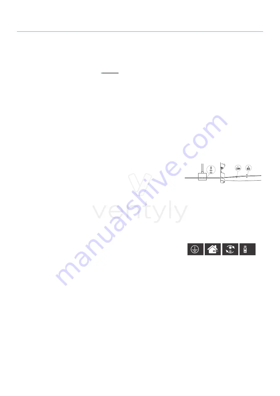
S
YMBOLOGY
RF
1- It has an earthing connection. The earth
wire (yellow / green) has to be connected to
the clip marked with.
2- It should only be installed in rooms where
direct contact with water is impossible.
3- The fan has the possibility of changing the
direction of rotation of the blades and thus
optimize the movement of the air.
4- Remote control with radio frequency. It
emits waves to the receiver.
ES
Lea todo este manual antes de empezar
la instalación y guarde estas instrucciones.
En caso de dudas, no dude en llamar a
nuestro departamento técnico.
Tenga en cuenta todas las especificaciones
del aparato que figuran en las etiquetas gris
pegada en el ventilador y en la hoja del dibu-
jo de instalación.
Para no dañar las superficies de la carcasa,
monte el motor sobre una superficie blanda o
utilice la espuma suministrada en el embala-
je. No apoye el motor de lado, ya que podría
dañarlo.
Para reducir el riesgo de lesiones person-
ales, fije el ventilador directamente a la es-
tructura de soporte del edificio de acuerdo
con estas instrucciones y use solamente los
herrajes suministrados.
Para evitar un posible choque eléctrico, an-
W
arning
A
tención
A
ttention


