Cabinet Instal lation
I-Ga te 4000 P R O Ins tall ation
5-2
Veraz Networks Inc. Proprietary
02041802-05
5.1.1. Bolting the ETSI Cabinet to a Concrete Floor
The procedure below describes anchoring the ETSI cabinet to a concrete floor.
To bolt the ETSI cabinet to a concrete floor:
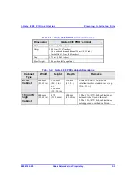
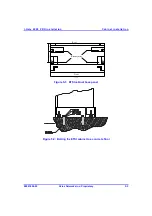
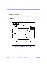
1. Mark out the floor in each equipment room for the cabinet's location. (See Figure
5-1 for locations of holes to be made in a concrete floor.) If installing more than
one ETSI cabinet, make sure they stand flush with one another.
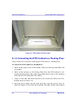
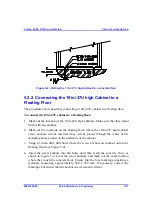
2. Using a 10mm drill bit, drill the mounting holes approximately 60mm deep (see
Figure 5-2). Clear out debris from the hole (use forced air).
3. Insert expansion shields into the holes.
4. Insert the anchoring screws into the holes. You may want to use pliers to squeeze
the lower end of the screws so that they go in more easily. Hammer them in
using light strokes until they protrude about 20 mm.
5. Remove the washers and nuts from the anchoring screws.
6. If the lower media gateway chassis is already installed, remove it by unscrewing
the screws on each side and pulling the media gateway chassis out. Make sure
that no cards are installed. Do not remove a media gateway with cards inside.
7. Position the ETSI cabinet so that holes "A" (see Figure 5-1) fit over the
anchoring screws.
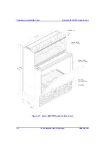
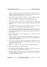
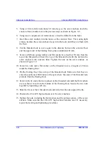
8. Level the cabinet by adjusting the leveling screws (Figure 5-3) with a 5 mm
Allen key. Use a carpenter's level or a plumb line for verification.
9. Make sure that there is at least a 0.5 to 1.0 mm space between the bottom of the
ETSI cabinet and the anchoring surface. Use pieces of sheet metal (or similar)
for this purpose.
10. Tighten the nuts on the anchoring screws, along with the flat washer and lock
washer. When tightening each screw, the ETSI cabinet must remain level.
11. If you have removed the lower media gateway chassis, replace it. To replace the
media gateway chassis, perform Step 6 in the reverse order.

