I-Ga te 4000 P R O Ins tall ation
Installin g the Chassis
02041802-05
Veraz Networks Inc. Proprietary
6-3
6.2. Attaching the Mounting Brackets to the
Chassis
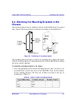
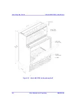
The mounting brackets must be attached to the I-Gate 4000 PRO before it's mounted
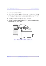
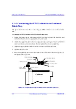
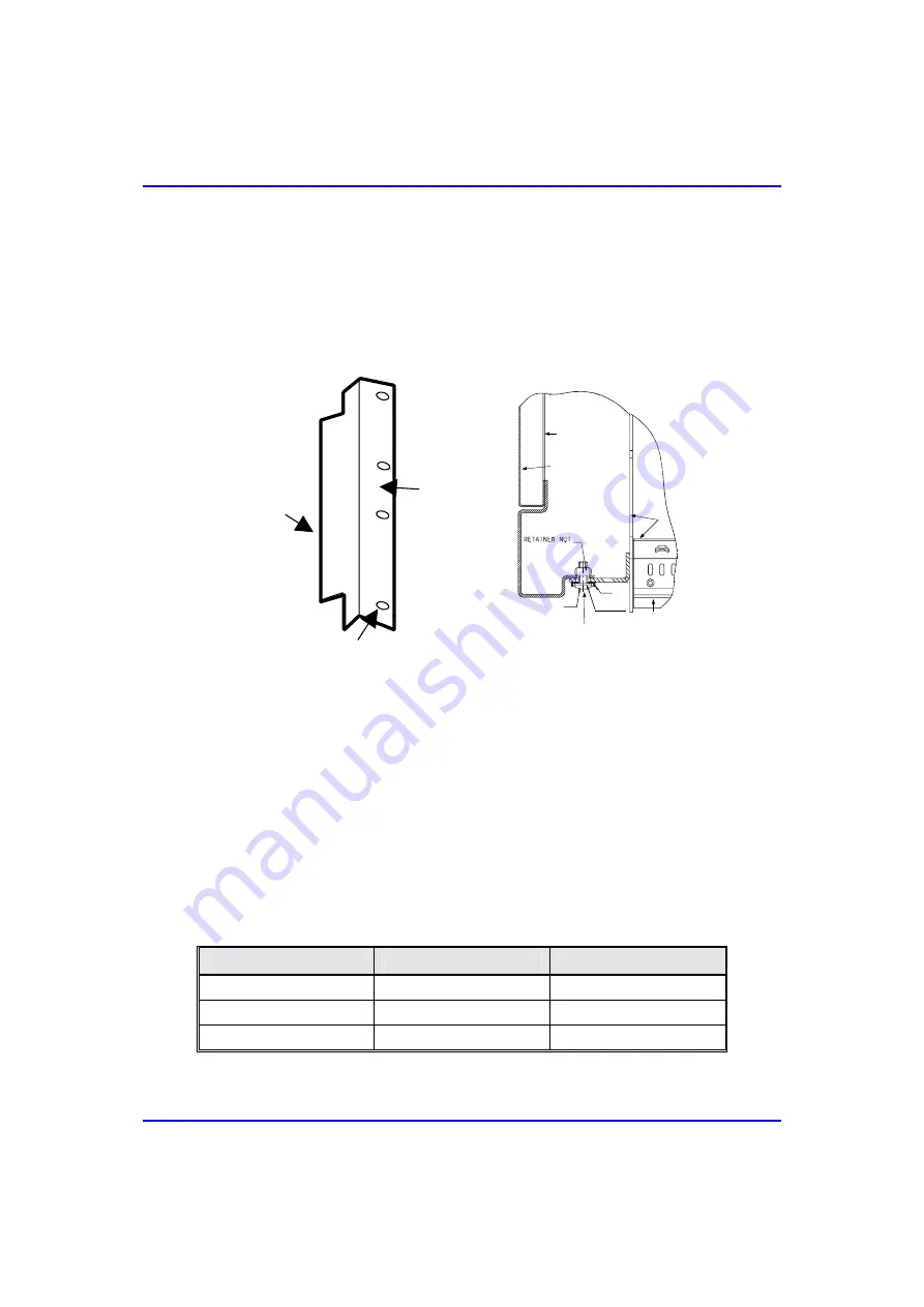
into a cabinet. The brackets must be mounted on the chassis as illustrated below.
Platform
mounting
surface
Cabinet
mounting
surface
Mounting pin
CABINET
SIDEWALL
SUBRACK
(CHASSIS)
CABINET
SUPPORT
MOUNTING PIN
FRONT EDGE OF
CHASSIS SEEN
FROM TOP
TOP VIEW
M6
SCREW M6 x 16
PLASTIC
WASHER M6
WASHER M6
Figure
6-2: Positioning of mounting brackets
The mounting position in Figure 6-2 allows the mounting pin to support the chassis
while the mounting hardware is being attached to the cabinet (until the M6 mounting
screws are securely fastened).
To attach the mounting brackets to the chassis:
1. Select the appropriate position for the mounting brackets. There are three sets of
pre-drilled holes on each side of the I-Gate 4000 PRO. These are the locations
for the mounting brackets. The three sets of holes are related to the type of
mounting (see Table 6-1).
Table
6-1: Holes of chassis mounting brackets
Type of Mounting
Location of holes
Number of holes
19" Front
3
ETSI Middle
3
NEBS Rear
4

