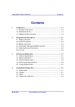
Conten ts
I-Ga te 4000 P R O Ins tall ation
ii
Veraz Networks Inc. Proprietary
02041802-05
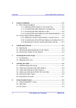
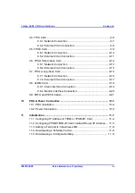
5 Cabinet
Installation................................................................................. 5-1
5.1. ETSI Cabinet Installation ................................................................... 5-1
5.1.1. Bolting the ETSI Cabinet to a Concrete Floor ...................... 5-2
5.1.2. Connecting the ETSI Cabinet to a Floating Floor................. 5-4
5.1.3. Connecting the ETSI Cabinet to a Wall ............................... 5-6
5.1.4. Connecting the ETSI Cabinet to an Overhead Cable Run ... 5-8
5.2. 19in./47U high Cabinet Installation..................................................... 5-9
5.2.1. Bolting the 19in./47U high Cabinet to a Concrete Floor ....... 5-9
5.2.2. Connecting the 19in./47U high Cabinet to a Floating Floor 5-11
5.2.3. Mounting the 19in./47U high Cabinets Rack-to-Rack......... 5-13
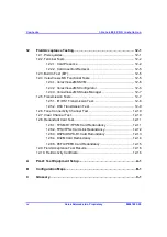
6 Installing
the
Chassis............................................................................. 6-1
6.1. Mounting Kit....................................................................................... 6-2
6.2. Attaching the Mounting Brackets to the Chassis ................................ 6-3
6.3. Inserting the Chassis into the Cabinet................................................ 6-4
7
Cooling System (Fan Trays) .................................................................. 7-1
7.1. Fan Operation.................................................................................... 7-2
7.2. Replacing a Fan Tray......................................................................... 7-4
8 Inserting
the
Cards ................................................................................. 8-1
8.1. Card Description and Layout.............................................................. 8-1
8.2. Card Layout Example for E1/DS1 Interface ....................................... 8-6
8.3. Card Layout Example for DS3 Interface............................................. 8-7
8.4. Card Layout Example for STM-1/OC-3 Interface................................ 8-8
8.5. Inserting the Main Cards.................................................................... 8-9
8.6. Inserting the I/O Cards..................................................................... 8-11
9 Connecting
the
Cables........................................................................... 9-1
9.1. D16I Card (E1/DS1 Trunks)............................................................... 9-2
9.2. D3IO Card ......................................................................................... 9-4
9.3. ST1I Card .......................................................................................... 9-5

