9.0 Wiring Diagrams
9.3
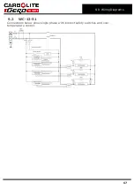
2- and 3-phase With Neutral
Each SSR is connected to a different phase. The control circuit is taken between L1 and
N.
Safety switch A applies for 2-phase. Safety switch B applies for 3-phase.
If type F1 fuse is present, one per phase if fitted.
If type F2 fuse is present, one is fitted; if type F3 fuse is present, one per phase is fitted.
Note that on 2- or 3-phase models there may be three separate neutrals taken to a
common supply terminal, depending on EMC filter requirements.
9.4
Independent Zones (control method C)
When this is ordered there are three independent thermocouples (instead of the four
shown) connected to the three controllers; the words “master” and “slave” may be
replaced by “centre” and “end”.
9.5
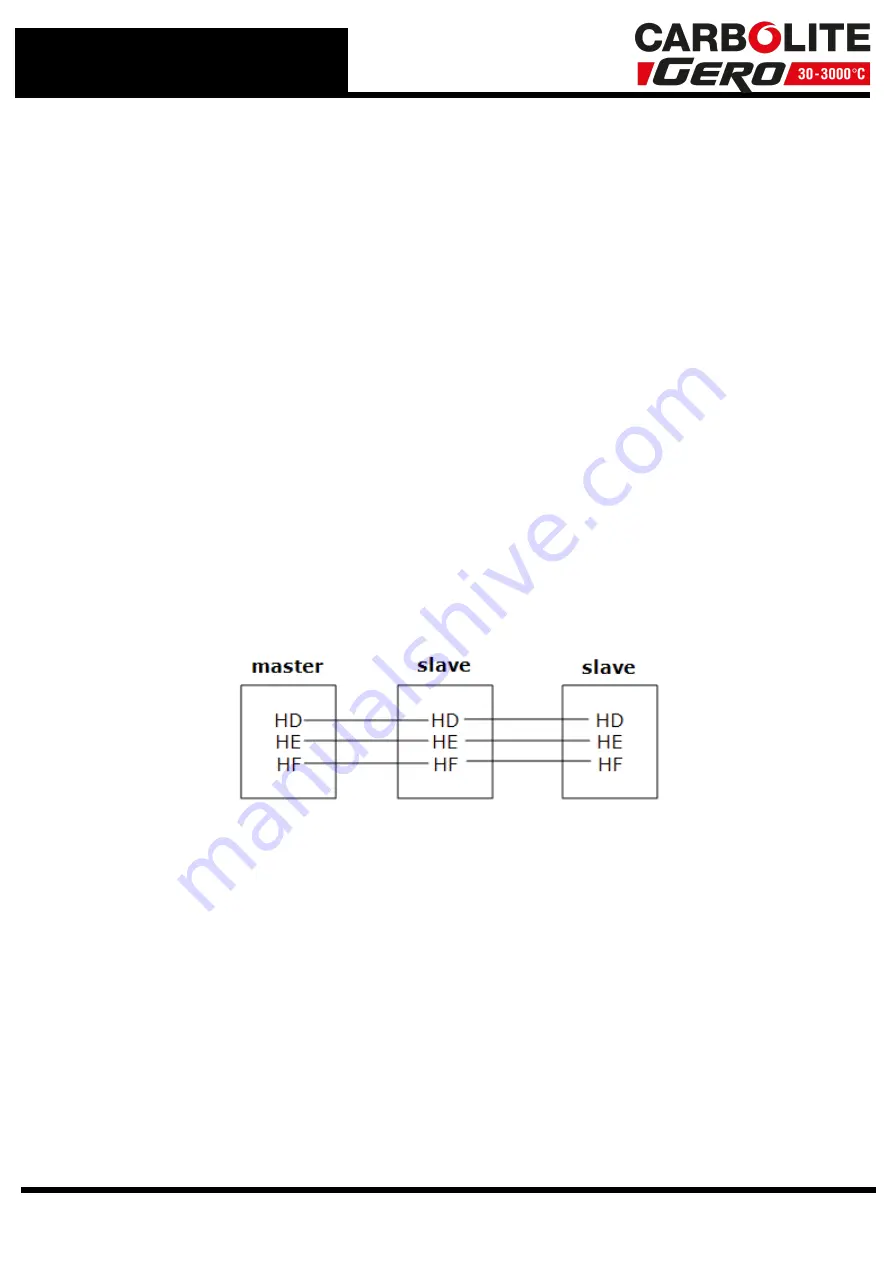
Control by Broadcast Comms (control method B)
When this is ordered there are three independent thermocouples connected to the three
controllers; the controllers are linked together (not shown), and remain “master” and
“slave”.
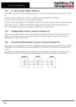
The communication between the controllers of the Eurotherm 3000 series is known as
Broadcast comms. The wiring connections between the controllers are as follows:
68

