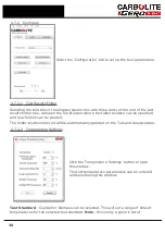
temperatures as outlined in the relative standard. Users can set their own test
parameter as described below.
Start Image Capture Temperature
- Select the temperature at which the software
starts to record images. It is advisable to start recording at a temperature that is as
close as possible the first sample melt point as this will reduce the number of stored
images. Each stored image requires 2 Mb of disc space.
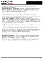
Test End Temperatures
- Set the maximum temperature the furnace will reach
during the test. Range 20 °C - 1600 °C.
Note
: Avoid operating the furnace at
unnecessarily high temperature as this will reduce the life of the elements, furnace
insulation and tube end seals. Set the target temperature as low as possible (depending
on your application) to gain the most economical use of your furnace.
Temperature Ramp Rate
- This is the rate of rise in temperature during the test.
Range 3 ° - 10 °C.
Note
: Avoid operating the furnace at unnecessarily fast ramp rates
as they may cause premature failure of the work tube. Set the controller ramp rate as
slow as possible (depending on your application) to gain the most economical use from
your furnace. The default setting is 7 °C/ minute.
Image Capture Interval
- Set temperature rate at which the software will record and
store an images i.e. If set at 5 °C an image will be captured every 5 °C throughout the
test. The maximum capture interval for automatic analysis should be no more than 5
°C/ minute. If a higher number than this is selected the software will prompt that
automatic analysis is not possible above this capture interval.
Range - 1 °C - 10 °C. Only whole numbers can be used, the smallest number that can
be entered is 1, the largest is 20. Each stored image requiring 2 Mb of disc space so it is
advisable to use large temperature intervals whenever possible.
Standby Temperature
- Set the temperature the furnace will maintain before and
after a test. Range 20 °C - 1600 °C.
Backlight Off Temperature
- Set the temperature at which the back lighting will be
switched off. After approximately 700 °C the radiant light from the elements will be
sufficient to light the chamber. Range 0 °C - 1000 °C
Save
- Once the settings have been adjusted to suit the test application, clicking the
save button will save the selected temperatures.
Note
: The Eurotherm temperature
controller is updated by the software and always holds the latest values.
31
Summary of Contents for CARBOLITE GERO CAF G5
Page 63: ...Fig 3 Front Tube Seal Assembly Fig 4 Door Arm Assembly 63 ...
Page 64: ...Fig 5a Camera Mounting Bracket Fig 5b Lens and Camera Assembly 64 ...
Page 65: ...Fig 5c Sliding the Camera Mounting Bracket Assembly onto the Door Arm 65 ...
Page 66: ...Fig 5d Securing the Camera Mounting Bracket Assembly to the Door Arm 66 ...
Page 67: ...Fig 5e Mounting the Lens and Camera Assembly 67 ...
Page 68: ...Fig 5f Lens and Camera Assembly in Position 68 ...
Page 69: ...Fig 6a Rear View of the Standard CAF G5 Furnace Showing Brick Box Assembly 69 ...
Page 71: ...Fig 7 Front Tube Seal Position 71 ...
Page 72: ...Fig 8 Tube End Seal Assembly Tightening Sequence Fig 9 Work Tube Front Support 72 ...
Page 73: ...Fig 10 Fitting the Door Arm Assembly Fig 10a Adjusting the Door Arm Assembly 73 ...
Page 74: ...Fig 11a Furnace Case and Controls 74 ...
Page 75: ...Fig 11b Gas Inlet Pipe Fig 12 Positioning the Furnace 75 ...
Page 77: ...Fig 13c Loading Samples into the Work Tube 77 ...
Page 78: ...Fig 16 File Folder 78 ...
Page 79: ...Fig 17 Door Arm Assembly Exploded View 79 ...
Page 82: ...SST DT HT FT Fig 18 Report Sheet Page 2 Side View Plan View Fig 19 Formed Wire Sample 82 ...
Page 83: ...Fig 20 Sample Carrier Sample Tiles and Sample Positions 83 ...
Page 84: ...Fig 21a Coal and Coke Test Piece Mould Fig 21b Biomass Test Piece Mould and Hand Press 84 ...
Page 85: ...Fig 22 Sample Loading Tool Fig 23 Camera Ethernet Connection 85 ...
Page 86: ...Fig 24 LED Driver Connection 86 ...
Page 87: ...Notes Service Record Engineer Name Date Record of Work ...


