background image

5.0

Maintenance

5.1

General Maintenance

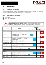
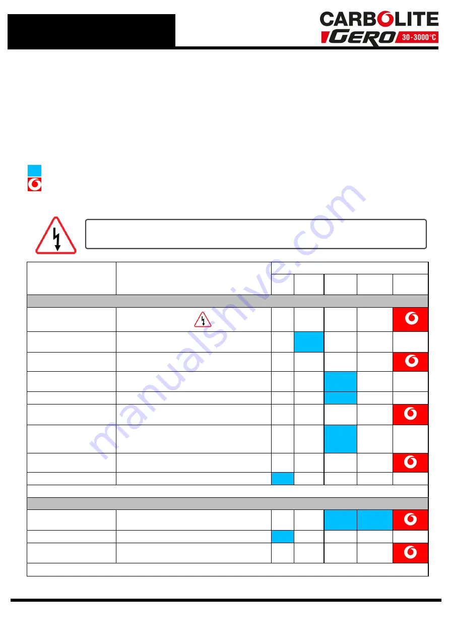
Preventive rather than reactive maintenance is recommended. The type and frequency
depends on the product use; the following are recommended.

5.2

Maintenance Schedule

CUSTOMER

QUALIFIED PERSONNEL

DANGER! ELECTRIC SHOCK

. Risk of fatal injury. Only electrically

qualified personnel should attempt these maintenance procedures.

Maintenance

Procedure

Method

Frequency

Daily Weekly Monthly

Bi-

Annually

Annually

Safety

Over-Temperature Safety
Circuit

Electrical measurement

Door Plug

Visual inspection, checking the seal and whether
it is free of any damage

Door Plug

Replacement where necessary

Extraction Pipe

Check that the connection is tight, and clean out
the pipe if necessary

Electrical Safety (external)

Visual check of external cables and plugs

Electrical Safety (internal)

Physically check all connections and cleaning of
the power plate area

Gas Safety (external)

Visually check that all pipework is in place and
free of damage. Physically check that all con-
nections are tight

Gas Safety (internal)

Leak test the gas system

Cooling Fans

Check whether the cooling fans are working

Function

Temperature Calibration

Tested using certified equipment, frequency
dependent on the standard required

Operational Check

Check that all functions are working normally

Operational Check

Thorough inspection and report incorporating a
test of all functions

46

Summary of Contents for CARBOLITE GERO CAF G5

Page 1: ...Installation Operation and Maintenance Instructions 1600 C Coal Ash Fusion Furnace CAF G5 CAF G5 MEN CAFG5 001_3508 17 09 2020 ...

Page 2: ... the Furnace 11 3 3 1 Element Fitting 11 3 3 2 Installing the Work Tube and Rear Seal Assembly 12 3 3 3 Fitting the Work Tube Front Seal Assembly 13 3 3 4 Fitting and Adjusting the Door Arm Assembly 13 3 3 5 Pressure Testing of the Work Tube Assembly 14 3 4 Positioning the Furnace 15 3 5 Electrical Connections 15 3 6 Voltage Level and Power Limit Settings 16 3 7 Exhaust Vent Connections 17 3 8 Gas...

Page 3: ...gs 34 4 7 2 6 Factory Reset 34 4 7 2 7 Backlight Intensity If Available 34 4 7 3 Test 35 4 7 3 1 Test Results Folder 35 4 7 3 2 New Test Name 35 4 7 3 3 Test Reference 36 4 7 3 4 Auto Analysis Selection 36 4 7 3 5 Start Test 36 4 7 3 6 Start Stop the Program 36 4 7 4 Analysis Automatic and Manual 36 4 7 4 1 Test Results Folder 37 4 7 4 2 Test Name 37 4 7 4 3 Automatic Analysis 38 4 7 4 4 Automatic...

Page 4: ... 6 1 Sample Carrier Tiles 50 5 6 2 Sample Preparation 50 5 6 3 Test Procedure 51 5 6 4 Interpretation of Results 51 5 6 4 1 Definitions 51 5 6 4 2 Documentation of Results 51 5 6 4 3 Temperature Limits 51 5 6 4 4 Deviations from Limits 52 5 7 Instrument Calibration Adjustment 52 5 8 After Sales Service 55 5 9 Recommended Spare parts and Consumables 55 6 0 Fault Analysis 56 A Furnace Does Not Heat ...

Page 5: ...sequence Fig 9 Work tube front support Fig 10 Fitting the door arm assembly Fig 10a Adjusting the door arm assembly Fig 11a Furnace case and controls Fig 11b Gas Inlet Pipe Fig 12 Positioning the furnace Fig 13a Positioning the samples on the sample carrier Fig 13b Loading samples into the work tube Fig 13c Loading samples into the work tube Fig 14 Set up options Fig 15a File name and sample ident...

Page 6: ...inated If any of the other three lights are illuminated see fig 11a then there is a fault do not use the furnace until the fault is rectified During Standby Mode only the green Standby Mode light should be illuminated If there are no lights illuminated or if any of the other three lights are illuminated see fig 11a including the green Standby Mode light then there is a fault do not use the furnace...

Page 7: ...tive To minimise the risks associated with CO it is most important that the furnace is installed and operated in accordance with this instruction manual If the furnace operator experiences any of the effects listed above the furnace must be isolated from the gas and electricity supplies immediately and expert advice sought For safety guidelines seek the gas manufacturers advice Table 1 Carbon mono...

Page 8: ... High Temperature Insulation Wool Refractory Ceramic Fibre better known as Alumina silicate wool ASW This product contains alumino silicate wool products in its thermal insulation These materials may be in the form of blanket or felt formed board or shapes slab or loose fill wool Typical use does not result in any significant level of airborne dust from these materials but much higher levels may b...

Page 9: ...the type of gases that are used to create the oxidising and reducing atmosphere and the control of those gases and the option of rear lighting particularly for lower temperature analysis such as Biomass Type 1 CO CO2 reducing gas and Air oxidising gas with N2 Purge gas With no rearlighting Compatible with both ASTM D1857 D1857M 04 2010 Standard Test Method for Fusibility of Coal and Coke Ash BS IS...

Page 10: ...uipment when moving it Use two or more people to carry the product where possible Carefully remove any packing material from inside and around the product before use Avoid damaging the surrounding insulation when removing packing materials Avoid applying force to internal components such as the work tube or insulation 3 2 Packing List The packaging should contain the following components 10 ...

Page 11: ... Window retaining ring spanner 1 off Cone mould 1 off 1 25 mm Allen key 1 off 150 mm length of Gold wire 1063 C fuse wire 1 off 150 mm length of Palladium wire 1554 C fuse wire 1 off Carbon Monoxide monitor 1 off RS232 Interface cable 1 off Ethernet connection cable Furnace Computer 1 off Computer 1 off Monitor 1 off Keyboard 1 off Mouse 1 off Memory Stick containing a copy of the software and ope...

Page 12: ...the furnace See fig 6a 6b Take the rear insulation assembly See Fig 2 Carefully insert the work tube and back seal assembly into the furnace from the back and slide it through the furnace until the work tube is protruding from the front The work tube is correctly positioned when the work tube insulating collar is in contact with the back face of the furnace heating chamber the work tube back suppo...

Page 13: ... the circumference of the tube within the aperture of the furnace heating chamber This can be tested for by lifting the work tube upwards from the support bracket only a slight gap should be observed between the work tube and the support bracket when the work tube is lifted as far as possible 3 3 4 Fitting and Adjusting the Door Arm Assembly Note the refractory door plug is fragile handle with car...

Page 14: ...mbly Note To ensure that the work tube assembly has been correctly installed it is necessary to pressure test the furnace prior to use Due to the high work tube temperatures used during CAF testing the tube O ring seals will deteriorate with time The furnace work tube also has a finite life and may eventually crack due to normal wear and tear It is necessary to conduct a pressure test of the work ...

Page 15: ...the hood extraction to ensure that fumes do not escape into the room As a precaution the furnace is supplied with a carbon monoxide detector If the CO detector is correctly installed it will alert the furnace operator in the event of a leak of carbon monoxide that is not removed by extraction Note The CO detector must be positioned and installed in accordance with the manufacturer s instructions s...

Page 16: ...furnace back panel The terminals are marked according to the power supply connect as shown in the table below The electrical supply must incorporate an earth ground Supply Terminal Label Cable Colour Supply Types Live Neutral Reversible or Live Live 1 phase L1 Brown to live to either power conductor For USA 200 240V connect L1 N L2 Blue to neutral to the other power conductor For USA 200 240V conn...

Page 17: ...ection 1 2 it is recommended that the vent tube is routed out of the building The furnace must always be positioned as recommended in section 3 4 The furnace has two exhaust vents the main vent at the back of the heating chamber and a safety pressure relief vent at the side of the furnace The purpose of the safety vent is to prevent dangerous pressure build up as the furnace warms up if the main v...

Page 18: ...djusted to ensure that equal mixtures of CO and CO2 are supplied The box also contains two non return valves to ensure that neither gas can flow back out of either inlet connection 3 8 2 Furnaces for H2 and CO2 Test Gases with CO2 Purge Gas Note The gas supply pressure required is 4 psi 0 276 bar and must not exceed this There are three gas connections on the side of the furnace CO2 oxidising atmo...

Page 19: ... the camera mounting bracket as shown in fig 5e and 5f l Secure the camera assembly in place with the four nuts and socket head screws provided l Screw the nuts onto the screw threads by hand then hold them in place using an 8 mm spanner l Tighten the screws using a 3 mm Allen key l To adjust the positioning of the camera loosen the outer screws to allow vertical movement or the inner screws to al...

Page 20: ...image can be focused on the screen It may be useful to take the weight of the camera in one hand while focusing with the other Once the image is focused on the screen the focus locking screw can now be tightened care must be taken not to over tighten these screws Note As the furnace warms up the work tube will increase slightly in length causing the camera focus to alter it may be necessary to re ...

Page 21: ...le with BS ISO 540 2008 The principle of operation is the same for both types The furnace is normally supplied programmed to operate between a pre determined setpoint start temperature and 1500 C at a ramp rate of 7 C minute The target temperature is set to 1500 C to avoid operating the furnace at high temperatures unnecessarily See section 4 7 2 2 The following text describes how to use the furna...

Page 22: ... 2002 the start temperature is adjustable from 400 C For furnaces constructed to use H2 and CO2 test gases with CO2 Purge gas compatible with BS ISO 540 2008 the start temperature is adjustable from 815 C To switch the furnace off set the instrument switch to off see fig 11a The case cooling fans remain on Leave the fans on until the furnace cools to below 300 C If the furnace is to be left off un...

Page 23: ...ent switch is turned on the control system will open the purge gas solenoid valve and purge the work tube for a duration of 5 minutes after which the system will go into standby mode and the green standby indicator will illuminate Note In the event of a power failure during standby the purge gas will flow continually until the power is restored When the power is restored the purge gas timer will r...

Page 24: ...h this to confirm the flow rates that give them satisfactory and consistent results Oxidising atmosphere If you are testing to ISO 540 2008 then this specification states that the flow rate is not critical Carbolite Gero would recommend using a low flow rate ASTM D1857 04 Reducing Oxidising Atmosphere If you are testing to ASTM D1857 04 then this specification states a regulated gas stream to prov...

Page 25: ... the unit prior to re staring any testing Gas system for leaks Work tube integrity Work tube end seals Exhaust outlet is not blocked For further details of what to do if the carbon monoxide sensor is activated please refer to the maintenance section in the manual 4 5 Loading Samples into the Work Tube Use the sample carrier and sample tiles provided Arrange the samples as shown in fig 13a It may b...

Page 26: ...ature Alarm Should a fault develop in the control system which causes the furnace to exceed its 1600 C limit an over temperature controller automatically shuts down the furnace and the over temperature warning light illuminates on the furnace control panel See fig 11a The over temperature controller is mounted inside the furnace case and is not accessible to the operator Turning the instrument swi...

Page 27: ...itical deformation temperatures to be entered manually along with individual sample identification The results form can then be saved and printed out in report form In both cases the software automatically starts and stops the furnace controller the start temperature and interval between images is adjustable to suit your requirements See section 4 7 2 2 The software is designed primarily to be use...

Page 28: ...llows to run a CAF test Sample Window Once the samples have been loaded into the furnace and the camera is positioned correctly a live image of the samples will be displayed in the sample window if sufficient light is available in the tube For temperatures below 700 C the rear lighting option if fitted should be used to provide illumination see section 4 7 2 7 28 ...

Page 29: ...r is shown by default but can be hidden if not required by selecting from the text menu Tools Tool Bars Show Hide Connection Status The bottom left of the software screen is the connection status indicators for the camera and the controller Green indicates connected red indicates disconnected 4 7 1 Process Tabs The CAF test software has been designed to maximise operator work flow by the use of pr...

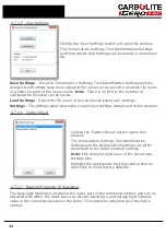
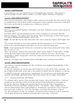
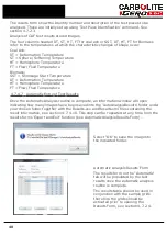
Page 30: ...n can be specified and new folders can be created The folder location entered will be automatically updated on the Test and Analysis tabs 4 7 2 2 Temperature Settings Click the Temperature Settings button to open this window The test temperature parameters can be entered and saved using this window Test Standard CoalAsh or Biomass can be selected This will set a range of default temperatures for t...

Page 31: ...plication to gain the most economical use from your furnace The default setting is 7 C minute Image Capture Interval Set temperature rate at which the software will record and store an images i e If set at 5 C an image will be captured every 5 C throughout the test The maximum capture interval for automatic analysis should be no more than 5 C minute If a higher number than this is selected the sof...

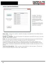
Page 32: ... test up to 20 sample codes can be entered Note No more than 8 samples can be used for automatic analysis and Carbolite Gero do not recommend more than 8 samples per test for manual analysis This automatically sets the number of test piece shown in the results window see section 4 7 4 and enters the test piece description into the results description column The number of samples selected also cont...

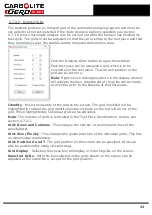
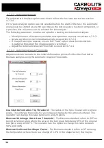
Page 33: ...n be made at any time prior to the analysis of the test pieces Identity this is the identity of the grid on the screen The grid identified will be highlighted in red and the grid identity number is shown on the top left corner of the grid When highlighted an individual grid can be adjusted Note The number of grids is controlled in the Test Piece Identification screen see section 4 7 2 3 Grid Rows ...

Page 34: ...tings The settings panel shows the current user settings loaded and its file location 4 7 2 6 Factory Reset Clicking the Factory Reset button opens this window The temperature Settings Test Identification Settings and the Analysis Grid settings can all be reset back to the factory default settings Note this does not delete any of the saved user settings files Highlight the appropriate test type an...

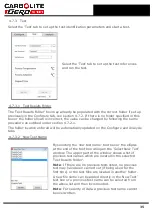
Page 35: ...ntered will be automatically updated on the Configure and Analysis tabs 4 7 3 2 New Test Name By selecting the new test name text box or the ellipsis at the end of the text box will open the Select New Test window The upper part of the window shows a list of previous test names which are located in the selected Test Results Folder Note If there are no previous tests listed no previous test may hav...

Page 36: ...es will be saved at the pre selected Image Capture Interval up to the ramp target temperature As the images are stored the black text box will flash across the top of the image window Both the Configure and Analysis tabs are disabled once recording has started 4 7 3 6 Start Stop the Program The furnace controller program can also be started and stopped independently of the CAF test software To sta...

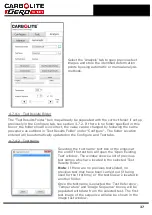
Page 37: ...r Location entered will be automatically updated on the Configure and Test tabs 4 7 4 2 Test Name Selecting the test name text box or the ellipsis at the end of the text box will open the Open Existing Test window The window shows a list of previous test names which are located in the selected Test Results Folder Note If there are no previous tests listed no previous test may have been carried out...

Page 38: ...e sequence scroll bar l Adjust the Automatic Analysis Threshold see section 4 7 4 4 4 7 4 4 Automatic Analysis Thresholds Adjustments can be made to the initial deformation points of either the Coal Ash or Biomass samples using the Automatic Analysis Thresholds Coal Ash Deformation Tip Threshold The radius of the tip is measured in camera pixels The software then looks for an increase in radius by...

Page 39: ...ll images have been analysed l Red indicates analysis failed in particular the image analysis This may be due to l Grids not positioned correctly l Lack of contrast between the sample and the background l Sample did not follow definition criteria Once the automatic analysis is completed the Progress and Status bars will both be shown in green if the analysis has been successful Note The test can b...

Page 40: ...7 Automatic Entry of Test Results Once the Automatic Analysis routine is complete an information window will open indicating how many images have been saved into the AutoAnalysisResults folder under your chosen folder together with the Results csv and Results xml files containing the result information see section 4 7 4 10 This step can be repeated at any time from the results forms Export and Exi...

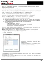
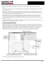
Page 41: ...under your chosen folder together with the Results csv and Results xml files containing the result information see section 4 7 4 10 A computer printout can be obtained by selecting Print the results are presented as a printdata pdf report sheet as shown in fig 18 4 7 4 8 Analysis Graph Form Additional deformation information can be viewed by selecting Analysis Graph Results button Parameters such ...

Page 42: ...ured line which is headed with its deformation identification i e SST DT HT FT Analysis Graph The graph shows any parameters or deformation points that have been selected from the Parameter selection or the Deformation selections Note No graph will be shown if none of the parameters are selected 4 7 4 9 Manual Entry of Analysis Results To enter results manually the manual analysis tab should be fi...

Page 43: ...nder your chosen folder together with the Results csv and Results xls files containing the result information see section 4 7 4 10 A computer printout can be obtained by selecting Print the results are presented as a printdata pdf report sheet as shown in fig 18 4 7 4 10 File Folders User test name folder This is the header folder which contains all the data and results for both the manual and aut...

Page 44: ...ined within this file is for software functionality only and is not relevant to the user Settings xml This file is created in the User Test Name folder It is written during the analysis phase When any settings are changed while in Analysis mode this file will be updated This could include changing test piece names grid parameters etc time stamp will indicate the last change AutoResults xml Automat...

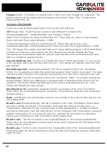
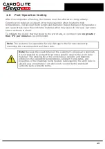
Page 45: ...be a cool down rate no greater than 5 C per minute is recommended Note The customer is responsible for any damage to the furnace caused by exceeding the recommended cool down rate Note Because the exact details of the customer s process are unknown it is not possible to account for process specific wear to the work tube material The working life of the work tube is variable and depends entirely on...

Page 46: ...or Plug Replacement where necessary Extraction Pipe Check that the connection is tight and clean out the pipe if necessary Electrical Safety external Visual check of external cables and plugs Electrical Safety internal Physically check all connections and cleaning of the power plate area Gas Safety external Visually check that all pipework is in place and free of damage Physically check that all c...

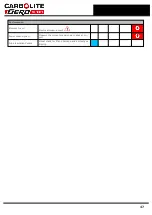
Page 47: ...Performance Element Circuit Electrical measurement Power Consumption Measure the current drawn on each phase cir cuit Tube Insulation Collars Visual check for fit and damage and correct pos itioning 47 ...

Page 48: ...r temperatures than you need See section 4 7 2 2 b Do not select unnecessarily fast ramp rates See section 4 7 2 2 There is a feature in the Software which allows the power from the elements to be adjusted This power limit is pre set at Carbolite Gero As the element performance declines the available power can be increased to compensate The maximum power figure available is 100 if the furnace perf...

Page 49: ...in the door plug ring A small amount of high temperature grease smeared over the back face groove side of the O ring will help to retain it 5 5 Cleaning the Viewing Window Clouding of the silica fused quartz viewing window may occur It is not certain whether this is caused by impurities in gases supplied into the furnace or by volatiles given off from the cones The effects of any volatiles in the ...

Page 50: ...e the window glass in position in the door plug ring and re fit the window retaining ring and tighten the window retaining ring to finger tight Using the tool provided tighten the window retaining ring to seal the viewing window Whilst tightening the window retaining ring hold the door plug in position to prevent it from rotating the gas inlet hole in the door plug must line up with the gas inlet ...

Page 51: ...les is required as they pass through their melt temperatures to enable the melting sequence to be assessed after completion of the test Set the digital image software to record at 1 C temperature intervals start ing at 20 C below the expected Gold melt point and finishing at 1580 C see section 4 6 5 6 4 Interpretation of Results 5 6 4 1 Definitions The individual melt temperature of a wire sample ...

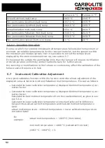
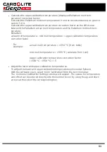
Page 52: ...y contact Carbolite Gero for further advice Any servicing or modifications to the furnace or controls may affect the calibration of the furnace and will require a re test 5 7 Instrument Calibration Adjustment A two point calibration function within the furnace controller allows adjustment of the displayed value at both the Gold and Palladium melt temperatures Proceed as follows l Calculate the low...

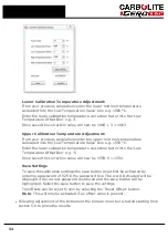
Page 53: ...pper calibration temperature correction factor For example actual melt temperature 1554 C from table mid melt temperature 1559 C calculate from test upper calibration temperature correction factor 1554 C 1559 C 5 l Adjust the lower and upper calibration temperatures To adjust the lower and upper calibration temperatures proceed as follows With the software open select tools calibration from the te...

Page 54: ... the lower calibration temperature correction factor into the Low Temperature Offset Box e g 5 Once saved the correction value will now be 1559 5 1554 Save Settings To save the calibration settings the save button must first be activated by entering a password of 525 in the password box The word Activated will be displayed if the correct password is entered and the save button will be highlighted ...

Page 55: ...e parts and Consumables Carbolite Gero can supply individual spare parts or a kit of the items most likely to be required Ordering a kit in advance can save time in the event of a breakdown Each kit comprises one thermocouple one solid state relay a set of elements and braids one of each type of internal fuse window glass gasket work tube gasket and door window O ring seal Other spare parts availa...

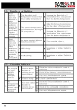
Page 56: ... circuit A heating element has failed 2 The HEAT lamp s is are OFF The controller shows a very high temperature or a code such as S br The thermocouple has broken or has a wiring fault A relay maybe faulty The SSR could be failing to switch on due to internal failure faulty logic from the controller or faulty controller The controller is not illuminated Check the supply fuses and any fuses in the ...

Page 57: ... round The controller maybe faulty Over Temperature controller may require resetting Located on the back of the power plate press the page and scroll buttons at the same time 2 The HEAT light does not go OFF when the instrument switch is switched off The SSR has failed ON Check for an accidental wiring fault which could have overloaded the SSR 3 Cooling fans not running Fan fuse F1 has failed Swit...

Page 58: ...en instrument switch is on and the computer is not connected No signal to switch lights on from the controller The controller is faulty LED s faulty Investigate or contact Carbolite Gero Faulty Wiring Investigate or contact Carbolite Gero D Computer Software 1 No image in software sample window from the camera Camera status indicator is showing red as disconnected Check the furnace instrument swit...

Page 59: ...rrect pressure Investigate or contact Carbolite Gero do not tamper with pressure settings as this may void warranty claims 2 Process gas not flowing No indication of gas flow though the flow meters Flow meter requires adjustment Adjust the flow rate to comply with working standards Faulty solenoid valve or solenoid coil connection Investigate or contact Carbolite Gero Gas oxidising reducing select...

Page 60: ...w continually It is recommended that the furnace is allowed to purge for at least 5 minutes before turning off the instrument switch The audible CO alarm can be switched off during this period by pressing the CO alarm reset switch The CO warning light will remain on during this period Identify the source of the leak before switching the furnace back on see section 3 3 The CO Sensor has overheated ...

Page 61: ...e Maximum external cabinet dimensions Height 804 mm Width 505 mm Case Depth 625 mm Overall Depth 1070 mm Work tube dimensions Internal Diameter 79 mm Length 650 mm Material Mullite 8 1 Environment The models listed in this manual contain electrical parts and should be stored and used in indoor conditions as follows Temperature 5 C 40 C Relative humidity Maximum 80 up to 31 C decreasing linearly to...

Page 62: ...9 0 Appendix The figures referred to in the previous text are listed below Fig 1 Element Wiring and Positions Fig 2 Work Tube and Back Plug Assembly 62 ...

Page 63: ...Fig 3 Front Tube Seal Assembly Fig 4 Door Arm Assembly 63 ...

Page 64: ...Fig 5a Camera Mounting Bracket Fig 5b Lens and Camera Assembly 64 ...

Page 65: ...Fig 5c Sliding the Camera Mounting Bracket Assembly onto the Door Arm 65 ...

Page 66: ...Fig 5d Securing the Camera Mounting Bracket Assembly to the Door Arm 66 ...

Page 67: ...Fig 5e Mounting the Lens and Camera Assembly 67 ...

Page 68: ...Fig 5f Lens and Camera Assembly in Position 68 ...

Page 69: ...Fig 6a Rear View of the Standard CAF G5 Furnace Showing Brick Box Assembly 69 ...

Page 70: ...Fig 6b Rear View of the CAF G5 Biomass Furnace with Rear Illumination Showing Brick Box Assembly 70 ...

Page 71: ...Fig 7 Front Tube Seal Position 71 ...

Page 72: ...Fig 8 Tube End Seal Assembly Tightening Sequence Fig 9 Work Tube Front Support 72 ...

Page 73: ...Fig 10 Fitting the Door Arm Assembly Fig 10a Adjusting the Door Arm Assembly 73 ...

Page 74: ...Fig 11a Furnace Case and Controls 74 ...

Page 75: ...Fig 11b Gas Inlet Pipe Fig 12 Positioning the Furnace 75 ...

Page 76: ...Fig 13a Positioning Samples on the Sample Carrier Fig 13b Loading Samples into the Mouth of the Work Tube 76 ...

Page 77: ...Fig 13c Loading Samples into the Work Tube 77 ...

Page 78: ...Fig 16 File Folder 78 ...

Page 79: ...Fig 17 Door Arm Assembly Exploded View 79 ...

Page 80: ... Reference ESG Ash Wood Identity Description SST DT HT FT 1 test piece 1 1209 1230 1242 1251 2 test piece 2 3 test piece 3 4 test piece 4 5 test piece 5 6 test piece 6 7 test piece 7 8 test piece 8 Temperature Scale Celsius SST Shrinkage Starting Temperature DT Deformation Temperature HT Hemisphere Temperature FT Flow fluid Temperature Fig 18 Report Sheet Page 1 80 ...

Page 81: ... April 2015 Test Start Time 15 03 Date of Analysis 23 April 2015 Time of Analysis 16 01 Test Name Carbolite Gero Biomass Test Reference Ash Wood Identity Description SST DT HT FT 1 test piece 1 1209 1230 1242 1251 81 ...

Page 82: ...SST DT HT FT Fig 18 Report Sheet Page 2 Side View Plan View Fig 19 Formed Wire Sample 82 ...

Page 83: ...Fig 20 Sample Carrier Sample Tiles and Sample Positions 83 ...

Page 84: ...Fig 21a Coal and Coke Test Piece Mould Fig 21b Biomass Test Piece Mould and Hand Press 84 ...

Page 85: ...Fig 22 Sample Loading Tool Fig 23 Camera Ethernet Connection 85 ...

Page 86: ...Fig 24 LED Driver Connection 86 ...

Page 87: ...Notes Service Record Engineer Name Date Record of Work ...

Page 88: ... us at the address below or ask your nearest stockist For preventive maintenance repair and calibration of all furnace and oven products please contact Carbolite Gero Service Telephone 44 0 1433 624242 Fax 44 0 1433 624243 Email ServiceUK carbolite gero com Carbolite Gero Ltd Parsons Lane Hope Hope Valley S33 6RB England Telephone 44 0 1433 620011 Fax 44 0 1433 621198 Email Info carbolite gero com...

Reviews: