Four pieces of each wire type are required, the samples are prepared as follows:
Cut a piece of wire 30 mm in length.
Using a pair of pin nose pliers, form one end of the wire into a coil so that when
standing on a flat surface it supports a 12 mm vertical column of wire. See fig 19.
The samples are positioned on the sample tiles, which are placed on the sample carrier
as shown in fig 20.
5.6.3
Test Procedure
The calibration test is based on BS ISO 540: 2008, Methods for Analysis and testing of
Coal and Coke. Conduct the test as follows:
l
Turn the furnace on, adjust the standby temperature to 815 °C and allow the fur-
nace to stabilise. As the furnace warms up prepare the sample carrier and samples
(section 5.6.2) and load into the work tube. Close the door and clamp securely to
steal the work tube (see section 4.5).
l
When the furnace has stabilised at 815 °C run a CAF test on a ramp rate of 7 °C/
minute to reach a maximum temperature of 1580 °C. During the test maintain an
'oxidising' atmosphere in the work tube (see section 4.6)
l
A digital image sequence of the samples is required as they pass through their melt
temperatures to enable the melting sequence to be assessed after completion of
the test. Set the digital image software to record at 1 °C temperature intervals, start-
ing at 20 °C below the expected Gold melt point and finishing at 1580 °C (see section
4.6).
5.6.4
Interpretation of Results
5.6.4.1
Definitions:
The "individual melt temperature" of a wire sample is the temperature at which the wire
sample, having fallen over onto the sample tile, melts and forms one or more stable
"balls" of molten material.
The "mid melt temperature" of a set of four wires is the average of the lowest and
highest of the four individual measured melt temperatures.
The "spread" of melt temperature is the difference between the highest and lowest of
the four individual melt temperatures.
The "actual" melt temperature is a fixed value for each wire sample type.
5.6.4.2
Documentation of Results
Record the individual melt temperature of each wire sample using the CAF Test
Software (see section 4.6 ) and print out the results using the report sheet. See fig 18.
For each wire type work out the mid melt temperature and the spread.
5.6.4.3
Temperature Limits
The following limits apply with respect to the melt (ball) temperatures of the wire
samples.
51
Summary of Contents for CARBOLITE GERO CAF G5
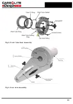
Page 63: ...Fig 3 Front Tube Seal Assembly Fig 4 Door Arm Assembly 63 ...
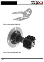
Page 64: ...Fig 5a Camera Mounting Bracket Fig 5b Lens and Camera Assembly 64 ...
Page 65: ...Fig 5c Sliding the Camera Mounting Bracket Assembly onto the Door Arm 65 ...
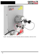
Page 66: ...Fig 5d Securing the Camera Mounting Bracket Assembly to the Door Arm 66 ...
Page 67: ...Fig 5e Mounting the Lens and Camera Assembly 67 ...
Page 68: ...Fig 5f Lens and Camera Assembly in Position 68 ...
Page 69: ...Fig 6a Rear View of the Standard CAF G5 Furnace Showing Brick Box Assembly 69 ...
Page 71: ...Fig 7 Front Tube Seal Position 71 ...
Page 72: ...Fig 8 Tube End Seal Assembly Tightening Sequence Fig 9 Work Tube Front Support 72 ...
Page 73: ...Fig 10 Fitting the Door Arm Assembly Fig 10a Adjusting the Door Arm Assembly 73 ...
Page 74: ...Fig 11a Furnace Case and Controls 74 ...
Page 75: ...Fig 11b Gas Inlet Pipe Fig 12 Positioning the Furnace 75 ...
Page 77: ...Fig 13c Loading Samples into the Work Tube 77 ...
Page 78: ...Fig 16 File Folder 78 ...
Page 79: ...Fig 17 Door Arm Assembly Exploded View 79 ...
Page 82: ...SST DT HT FT Fig 18 Report Sheet Page 2 Side View Plan View Fig 19 Formed Wire Sample 82 ...
Page 83: ...Fig 20 Sample Carrier Sample Tiles and Sample Positions 83 ...
Page 84: ...Fig 21a Coal and Coke Test Piece Mould Fig 21b Biomass Test Piece Mould and Hand Press 84 ...
Page 85: ...Fig 22 Sample Loading Tool Fig 23 Camera Ethernet Connection 85 ...
Page 86: ...Fig 24 LED Driver Connection 86 ...
Page 87: ...Notes Service Record Engineer Name Date Record of Work ...

