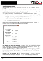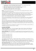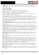
Save Settings
To save the calibration settings, the save button must first be activated by entering a
password of 525 in the password box. The word 'Activated' will be displayed if the
correct password is entered and the save button will be highlighted. Select the save
button to save the settings.
The Eurotherm temperature controller always holds the latest values.
5.4
Checking and Replacing the Door 'O' Ring Seal
Warning: Wear neoprene gloves before handling the 'O' ring seals - see section 1.5.
Regularly check the condition of the door 'O' ring seal, see fig 17. The 'O' ring seal is a
push fit into the groove in the door plug ring, carefully remove it by hand, do not use
sharp tools as this could damage the seal and the door plug ring.
Inspect the condition of the door 'O' ring seal, it must be uniform in shape and section,
and free from cuts, cracks, dust and grit. If the seal is damaged replace it, a faulty seal
can cause leakage of carbon monoxide during testing. See section 1.2.
Clean the seal faces of the door plug ring and work tube front seal assembly, these
must be free from dust, grit, chips and scratches. Any damage to these faces can cause
leakage of carbon monoxide during testing and must be rectified.
To re-fit the door 'O' ring seal simply push it into the groove in the door plug ring. A
small amount of high temperature grease smeared over the back face (groove side) of
the 'O' ring will help to retain it.
5.5
Cleaning the Viewing Window
Clouding of the silica (fused quartz) viewing window may occur. It is not certain whether
this is caused by impurities in gases supplied into the furnace or by volatiles given off
from the cones. The effects of any volatiles in the cones can be minimised by allowing a
couple of minutes for the cones to burn off before closing the door after loading the
furnace. A cloudy glass absorbs more heat than a clear one and heat accelerates the
corrosion of the surface, regular cleaning of the glass before a test can avoid
cumulative effects.
5.5.1
To remove the viewing window for cleaning or replacement:
Ensure that the furnace is cool and the electricity and gas supply is isolated.
Remove the camera and mounting bracket assembly, see fig 5b and 5c.
Warning: Wear neoprene gloves before handling the 'O' ring seals - see section 1.5.
Withdraw the door assembly fully from the work tube to avoid damaging the door plug.
Hold the door arm securely and using the tool provided unscrew the viewing window
retaining ring anti clockwise. Remove the retaining ring carefully, noting the positions of
the window 'O' ring seal, window glass and window glass gasket. See fig 17. Hold the
window by the edges and avoid touching the glass surface, traces of perspiration can
etch the surface of the glass when it is heated.
49
Summary of Contents for CARBOLITE GERO CAF G5
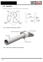
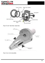
Page 63: ...Fig 3 Front Tube Seal Assembly Fig 4 Door Arm Assembly 63 ...
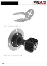
Page 64: ...Fig 5a Camera Mounting Bracket Fig 5b Lens and Camera Assembly 64 ...
Page 65: ...Fig 5c Sliding the Camera Mounting Bracket Assembly onto the Door Arm 65 ...
Page 66: ...Fig 5d Securing the Camera Mounting Bracket Assembly to the Door Arm 66 ...
Page 67: ...Fig 5e Mounting the Lens and Camera Assembly 67 ...
Page 68: ...Fig 5f Lens and Camera Assembly in Position 68 ...
Page 69: ...Fig 6a Rear View of the Standard CAF G5 Furnace Showing Brick Box Assembly 69 ...
Page 71: ...Fig 7 Front Tube Seal Position 71 ...
Page 72: ...Fig 8 Tube End Seal Assembly Tightening Sequence Fig 9 Work Tube Front Support 72 ...
Page 73: ...Fig 10 Fitting the Door Arm Assembly Fig 10a Adjusting the Door Arm Assembly 73 ...
Page 74: ...Fig 11a Furnace Case and Controls 74 ...
Page 75: ...Fig 11b Gas Inlet Pipe Fig 12 Positioning the Furnace 75 ...
Page 77: ...Fig 13c Loading Samples into the Work Tube 77 ...
Page 78: ...Fig 16 File Folder 78 ...
Page 79: ...Fig 17 Door Arm Assembly Exploded View 79 ...
Page 82: ...SST DT HT FT Fig 18 Report Sheet Page 2 Side View Plan View Fig 19 Formed Wire Sample 82 ...
Page 83: ...Fig 20 Sample Carrier Sample Tiles and Sample Positions 83 ...
Page 84: ...Fig 21a Coal and Coke Test Piece Mould Fig 21b Biomass Test Piece Mould and Hand Press 84 ...
Page 85: ...Fig 22 Sample Loading Tool Fig 23 Camera Ethernet Connection 85 ...
Page 86: ...Fig 24 LED Driver Connection 86 ...
Page 87: ...Notes Service Record Engineer Name Date Record of Work ...

