5.8
After-Sales Service
Carbolite Gero Service has a team of Service Engineers who can offer repair, calibration
and preventive maintenance of furnace and oven products both at the Carbolite Gero
factory and at customers’ premises throughout the world. A telephone call or email
often enables a fault to be diagnosed and the necessary parts to be despatched.
In all correspondence please quote the serial number and model type given on the
rating label of the product. The serial number and model type are also given on the
back of this manual when supplied with the product.
Carbolite Gero Service and Carbolite Gero contact information can be found on the back
page of this manual.
5.9
Recommended Spare parts and Consumables
Carbolite Gero can supply individual spare parts, or a kit of the items most likely to be
required. Ordering a kit in advance can save time in the event of a breakdown. Each kit
comprises one thermocouple, one solid state relay, a set of elements and braids, one of
each type of internal fuse, window glass gasket, work tube gasket and door/ window 'O'
ring seal. Other spare parts available are:
l
Work tube
l
Work tube 'O' ring seal
l
Viewing window glass
l
Door plug
l
Rear plug
l
Sample carrier
l
Sample tile
l
Cone mould (specify which cone mould is required, i.e. 12.7 mm or 19.0 mm high).
All spare parts will be supplied with service information where applicable.
When ordering spare parts please quote the serial number, model type and voltage
given on the rating label of the furnace.
For further information contact our service division at the address given at the end of
this manual.
55
Summary of Contents for CARBOLITE GERO CAF G5
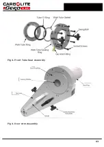
Page 63: ...Fig 3 Front Tube Seal Assembly Fig 4 Door Arm Assembly 63 ...
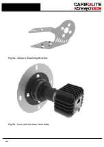
Page 64: ...Fig 5a Camera Mounting Bracket Fig 5b Lens and Camera Assembly 64 ...
Page 65: ...Fig 5c Sliding the Camera Mounting Bracket Assembly onto the Door Arm 65 ...
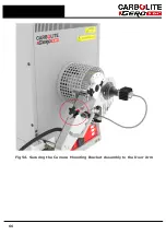
Page 66: ...Fig 5d Securing the Camera Mounting Bracket Assembly to the Door Arm 66 ...
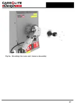
Page 67: ...Fig 5e Mounting the Lens and Camera Assembly 67 ...
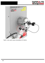
Page 68: ...Fig 5f Lens and Camera Assembly in Position 68 ...
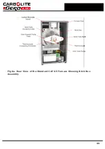
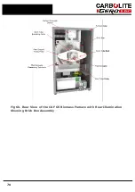
Page 69: ...Fig 6a Rear View of the Standard CAF G5 Furnace Showing Brick Box Assembly 69 ...
Page 71: ...Fig 7 Front Tube Seal Position 71 ...
Page 72: ...Fig 8 Tube End Seal Assembly Tightening Sequence Fig 9 Work Tube Front Support 72 ...
Page 73: ...Fig 10 Fitting the Door Arm Assembly Fig 10a Adjusting the Door Arm Assembly 73 ...
Page 74: ...Fig 11a Furnace Case and Controls 74 ...
Page 75: ...Fig 11b Gas Inlet Pipe Fig 12 Positioning the Furnace 75 ...
Page 77: ...Fig 13c Loading Samples into the Work Tube 77 ...
Page 78: ...Fig 16 File Folder 78 ...
Page 79: ...Fig 17 Door Arm Assembly Exploded View 79 ...
Page 82: ...SST DT HT FT Fig 18 Report Sheet Page 2 Side View Plan View Fig 19 Formed Wire Sample 82 ...
Page 83: ...Fig 20 Sample Carrier Sample Tiles and Sample Positions 83 ...
Page 84: ...Fig 21a Coal and Coke Test Piece Mould Fig 21b Biomass Test Piece Mould and Hand Press 84 ...
Page 85: ...Fig 22 Sample Loading Tool Fig 23 Camera Ethernet Connection 85 ...
Page 86: ...Fig 24 LED Driver Connection 86 ...
Page 87: ...Notes Service Record Engineer Name Date Record of Work ...

