1.2
Carbon Monoxide Warning
Operation of the CAF furnace involves the use of carbon monoxide.
Carbon monoxide is a product of reaction of H
2
and CO
2
.
Carbon monoxide (CO) is a colourless, odourless, tasteless and inflammable gas which
is acutely toxic. CO is introduced into the blood stream through the lungs and binds with
the haemoglobin preventing it from carrying oxygen around the body. This can result in
rapid damage to body tissues due to oxygen starvation. Since CO is an accumulating
toxin it can be dangerous even when present in quite low concentrations over long
periods of time. Individuals vary considerably in their reactions to concentrations of
toxic gases; table 1 shows the typical effects of cumulative CO exposure.
Information extracted from Guidance Note EH43 (1996) from the Health and
Safety Executive.
To minimise the risks associated with CO it is most important that the furnace is
installed and operated in accordance with this instruction manual. If the furnace
operator experiences any of the effects listed above, the furnace must be isolated from
the gas and electricity supplies immediately and expert advice sought. For safety
guidelines seek the gas manufacturers advice.
Table 1. Carbon monoxide in air:
Parts per
million
Effect
50
Recommended Exposure Limit (8 hours time weighted average
concentration)
200
Headache after approximately 7 hours if resting or after 2 hours
exertion
400
Headache with discomfort with possibility of collapse after 2 hours at
rest or 45 minutes exertion.
1200
Palpitations after 30 minutes at rest or 10 minutes exertion.
2000
Unconscious after 30 minutes at rest or up to 10 minutes exertion.
For further information refer to:
l
Guidance Note EH43 (1996) from the Health and Safety Executive. ISBN 0 11
883597 1
l
EH40/ 2005 Workplace Exposure Limits 2011. ISBN 978 0 7176 6446 7
7
Summary of Contents for CARBOLITE GERO CAF G5
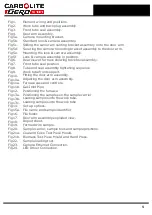
Page 63: ...Fig 3 Front Tube Seal Assembly Fig 4 Door Arm Assembly 63 ...
Page 64: ...Fig 5a Camera Mounting Bracket Fig 5b Lens and Camera Assembly 64 ...
Page 65: ...Fig 5c Sliding the Camera Mounting Bracket Assembly onto the Door Arm 65 ...
Page 66: ...Fig 5d Securing the Camera Mounting Bracket Assembly to the Door Arm 66 ...
Page 67: ...Fig 5e Mounting the Lens and Camera Assembly 67 ...
Page 68: ...Fig 5f Lens and Camera Assembly in Position 68 ...
Page 69: ...Fig 6a Rear View of the Standard CAF G5 Furnace Showing Brick Box Assembly 69 ...
Page 71: ...Fig 7 Front Tube Seal Position 71 ...
Page 72: ...Fig 8 Tube End Seal Assembly Tightening Sequence Fig 9 Work Tube Front Support 72 ...
Page 73: ...Fig 10 Fitting the Door Arm Assembly Fig 10a Adjusting the Door Arm Assembly 73 ...
Page 74: ...Fig 11a Furnace Case and Controls 74 ...
Page 75: ...Fig 11b Gas Inlet Pipe Fig 12 Positioning the Furnace 75 ...
Page 77: ...Fig 13c Loading Samples into the Work Tube 77 ...
Page 78: ...Fig 16 File Folder 78 ...
Page 79: ...Fig 17 Door Arm Assembly Exploded View 79 ...
Page 82: ...SST DT HT FT Fig 18 Report Sheet Page 2 Side View Plan View Fig 19 Formed Wire Sample 82 ...
Page 83: ...Fig 20 Sample Carrier Sample Tiles and Sample Positions 83 ...
Page 84: ...Fig 21a Coal and Coke Test Piece Mould Fig 21b Biomass Test Piece Mould and Hand Press 84 ...
Page 85: ...Fig 22 Sample Loading Tool Fig 23 Camera Ethernet Connection 85 ...
Page 86: ...Fig 24 LED Driver Connection 86 ...
Page 87: ...Notes Service Record Engineer Name Date Record of Work ...


