7.0 Repairs and Replacements
7.6
Element Replacement (Laboratory Models)
See section 7.2 - wearing a face mask is required.
The chambers have two side-mounted refractory panels in which coiled heating
elements are inserted; each side contains 3 “hairpin” elements giving 6 coils of heating
wire per side.
Disconnect the furnace from the electrical supply and remove the back panel.
Make a written plan showing ALL the element and thermocouple connections. It is
important to make this plan for each individual furnace.
Loosen the clamping screws onto the terminal blocks holding the faulty element. If
necessary straighten the bent ends of the wire.
From within the chamber, carefully lift the elements out of the channels in the element
carrier. Each element is retained at the front by the unwound portion being trapped
between the front brickwork and the element carrier.
If necessary, use a sharp knife to relieve the element carrier at the front with a 45° cut
on the “bridge” portion to aid withdrawal of the element.
Take care to minimise damage to the delicate fibre element carrier.
Finally pull the tails out through the back insulation.
Fit the new element. It may be helpful to feed a flexible plastic or nylon tube, with a
bore just larger than the element wire, through the terminal block into the chamber. Fit
the element wire into this tube; as the tube is withdrawn, the element tail can be pulled
through the terminal block.
When both parts of the element are located in the channels gently pull the ends of the
element until the first spiral is level with the back chamber wall insulation. If the element
spirals are pulled too far into the cavity between the back insulation and the element
carrier, overheating may occur.
If necessary, bend the element tails, supporting the wire so as not to damage the
insulation. Cut off any excess wire and firmly tighten the terminal block screws.
Refit the back panel.
Check that the furnace is controlling properly to rule out the possibility that previous
element failed because of a fault elsewhere in the control circuit
7.7
Fuse Replacement
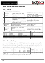
Fuses are marked on the wiring diagram with type codes, e.g. F1, F2. For more
information on fuses refer to section 10.0.
Depending on model and voltage, the different fuse types may or may not be fitted.
If any fuse has failed, it is advisable for an electrician to check the internal circuits.
Replace any failed fuses with the correct type. For safety reasons do not fit larger
capacity fuses without first consulting Carbolite Gero.
22
Summary of Contents for CARBOLITE GERO CWF 13/65
Page 34: ......
Page 35: ...Notes Service Record Engineer Name Date Record of Work ...

