3.8.13
Alarms
Alarms are used to alert the operator when a pre-set level has been exceeded or a
function error has occurred such as a sensor break. They are indicated by a flashing red
ALM (Alarm) indicator. The alarm may also switch an output – usually a relay to allow
external devices to operate when an alarm occurs. Alarms only operate if they have
been configured and are dependent on customer requirements.
How to acknowledge an alarm will depend on the type of latching which has been
configured. A non-latched alarm will reset itself when the alarm condition is removed. A
latched alarm requires acknowledgement with the 'ACK' function before it is reset.
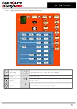
If an alarm has been activated, the red 'ALM' indicator will flash and the text will
indicate the type of alarm.
To acknowledge an alarm and cancel the 'ALM' indicator, press
and
together.
3.8.14
Program Example 1
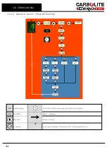
The following sequence of entries creates and runs the program shown graphically
below.
1. Turn the controller SP down to '0' by pressing down
.
2. Press page
until 'Prog Segments Used' is displayed. On P10 or P25 models press
up
or down
to select a new program number, (a program with only 1 segment).
3. Press scroll
until 'Holdback Value' is displayed. Default ‘0’ degrees.
4. Press scroll
until 'Ramp Units' is displayed. Press up
or down
to set to ‘Min’
5. Press scroll
until 'Cycles' is displayed. Default ‘1’
6. Press scroll
until 'Segment 1' is displayed
7. Press scroll
until 'Segment Type' is displayed. Press up
or down
to select
'Rate"
8. Press scroll
until 'Holdback Type' is displayed. Default ‘Off’
9. Press scroll
until 'Target SP' is displayed. Press up
or down
to set to ‘400’
degrees.
10. Press scroll
until 'Ramp Rate' is displayed. Press up
or down
to set to ‘5.0’
degrees per minute.
Repeat steps 6 to 10 for 4 more segments. Set 'Holdback' to the default ‘Off’. Enter the
following parameters and values:
Segment Type Dwell Duration ‘30:00.0’ minutes
Segment Type Step Target SP ‘600’ degrees
Segment Type Dwell Duration ‘30:00.0’ minutes
Segment Type Time Target SP ‘200’ degrees, Duration ‘2:00:0’ hours
Finish the program with an 'End' segment:
23
3.0 3508 Controller
Summary of Contents for CARBOLITE GERO HTF 18/8
Page 7: ...Caution Double Pole Neutral Fusing 7 1 0 Symbols and Warnings ...
Page 37: ...Power Limit View 37 4 0 3508 Dual Loop Cascade ...
Page 59: ...59 8 0 Repairs and Replacements ...
Page 64: ...10 0 Wiring Diagrams GR Y Green Yellow 64 ...
Page 68: ......
Page 69: ...Notes Service Record Engineer Name Date Record of Work ...


